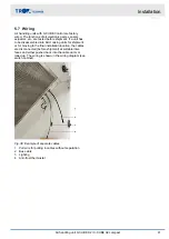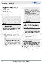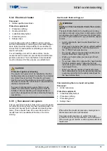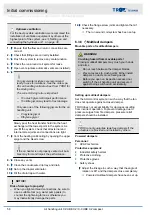
Connecting cables
Fig. 39: Connection of the cables
1.
Place the AHU casing units as close together as
possible so that you can connect the cables.
Note:
If there is not much space, you can also
connect the cables inside the AHU casing unit.
2.
First run the cables in sections through the air
handling unit to the switch cabinet without discon-
tinuities, see wiring diagram. Where cables have
to be pulled in, e.g. behind heat recovery units, a
pull wire is provided for pulling in the cable.
3.
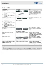
Then connect the separate cables according to
the type of plug and the colours of the cable and
‘Interface connections’ on page 42
.
Connect only cables with the same code.
4.
When you push the AHU casing units together,
feed the cables into the mesh cable trays and be
careful to not damage any cables.
5.8 Connecting the air handling unit to
the power supply
Electrical connection
DANGER!
Danger of death due to electric current!
Danger of electric shock! Do not touch any live com-
ponents!
–
Only a skilled qualified electrician must connect
the power supply.
–
For air handling units with integral controls use
the circuit diagram in this manual,
cable documentation’ on page 3
–
Lay connecting cables in such a way that they
cannot be accidentally damaged by mechanical
impact or by heat.
–
Bridge all non-conductive joints, such as con-
necting frames, flexible connectors and anti-
vibration elements, with an equipotential bonding
cable.
–
Earth the air handling unit according to the state
of the art.
–
Secure all connections so that they cannot come
loose.
–
When you connect any electrical components,
follow the manufacturers' specifications, the local
regulations and codes of good practice (DIN/
VDE), and the general recommendations for
avoiding electromagnetic interference,
–
If an AHU is installed outdoors, do not neglect
the effects of weather on the unit (rain, snow,
wind, sun etc.).
If you have to attach brackets or fasteners to the
AHU panels or frame, use only those specially
approved for your AHU as otherwise there is a risk of
leakages. Avoid screw joints that pierce the outer
shell of the unit; if you cannot avoid them, then at
least seal them to prevent the ingress of water. The
minimum protection level is IP 65.
1.
Units with controls
The electrical circuit diagrams and terminal
plans can be found in the circuit diagram
included in the supply package.
Connect the electrical components, such as the
electric air heater, electric motor, and actuator.
2.
Include the air handling unit in the equipotential
bonding arrangement.
3.
Test protective conductors and insulation resist-
ance to EN 60204 (VDE 0113). Take the appro-
priate safety precautions!
Installation
Connecting the air handling unit to the power su...
Air handling unit X-CUBE X2 / X-CUBE X2 compact
43
Содержание X-CUBE X2
Страница 69: ...Appendix Appendix Air handling unit X CUBE X2 X CUBE X2 compact 69...
Страница 71: ...A Adjusting the storage mass Adjusting the storage mass Air handling unit X CUBE X2 X CUBE X2 compact 71...
Страница 72: ...Montageanleitung Mounting Instructions KLINGENBURG Ausrichtung der Speichermasse Adjustment of storage mass...


