background image


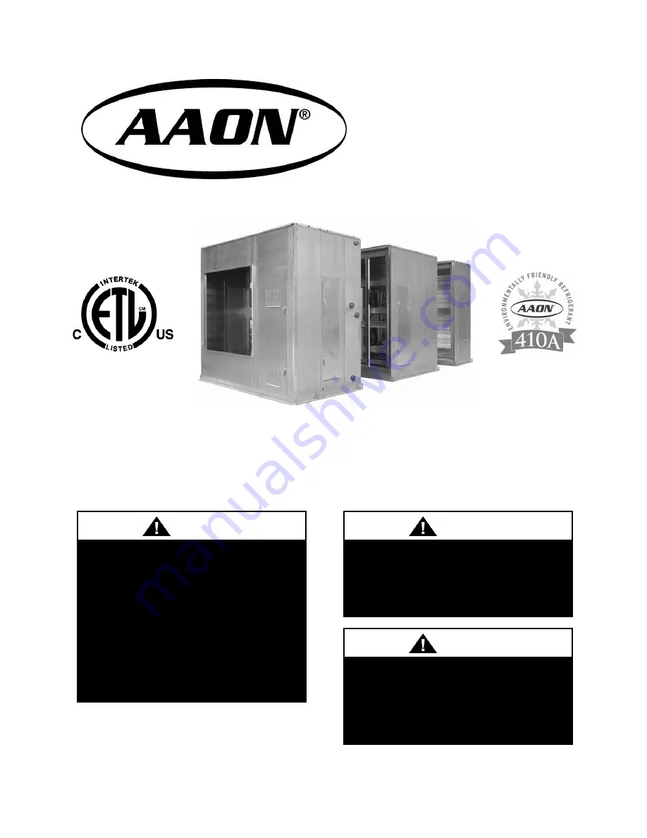
M3 Series 

Modular Indoor and Outdoor Air Handling Units 


Installation, Operation 

& Maintenance 


QUALIFIED INSTALLER 

 
Improper 

installation, 

adjustment, 

alteration,  service  or  maintenance 
can 

cause 

property 

damage, 

personal injury or loss of life.  Startup 
and  service  must  be  performed  by  a 
Factory  Trained  Service  Technician. 
A  copy  of  this  IOM  should  be  kept 
with the unit. 


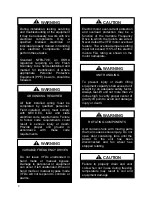
WARNING


If the information in this manual is not 
followed  exactly,  a  fire  or  explosion 
may result causing property damage, 
personal injury or loss of life. 


WARNING


FOR YOUR SAFETY 


Do not store or use gasoline or other 
flammable  vapors  and  liquids  in  the 
vicinity of this or any other appliance. 


WARNING


Содержание M3 Series

Страница 1: ...f life Startup and service must be performed by a Factory Trained Service Technician A copy of this IOM should be kept with the unit WARNING If the information in this manual is not followed exactly a fire or explosion may result causing property damage personal injury or loss of life WARNING FOR YOUR SAFETY Do not store or use gasoline or other flammable vapors and liquids in the vicinity of this...

Страница 2: ...Description 30 Energy Recovery Module Feature Description 33 Return Fan Module Feature Description 35 General Description 37 Receiving 37 Storage 38 Installation 38 Location Clearances 38 Rigging 39 Module Location 40 Module Assembly 40 Module Disassembly 44 Spring Isolator Adjustment 44 Blower Wheels 45 Air Adjustment 45 Condensate Drains 46 Draw Through P Trap Example 48 Blow Through P Trap Exam...

Страница 3: ...rain Pans 60 E Coated Coil Cleaning 61 Winterizing Coils 62 Removing Coils 62 Doors Panels 63 Outside Opening Door and Panel 64 Filters 64 Replacement Parts 65 M3 Series Startup Form 68 Maintenance Log 71 Literature Change History 72 R57350 Rev D 160822 ...

Страница 4: ...e 13 Lifting Lugs and Bolts 42 Figure 14 Come Along Putting Together Modules 42 Figure 15 Pulling Sections Together 43 Figure 16 Fastening Sections Together 43 Figure 17 Attaching Splice 43 Figure 18 Attaching Corner Rail Cover 43 Figure 19 Attaching Base Splice 44 Figure 20 Blower Spring Isolator 44 Figure 21 Spring Isolator Adjustment 45 Figure 22 Supply Fan Banding 46 Figure 23 Draw Through Dra...

Страница 5: ...5 Figure 34 Blower Rotation 59 Figure 35 Coil Removal 63 Figure 36 Access Door Panel Removal 64 Figure 37 Access Door 64 Figure 38 Cartridge Bag Filter Layout Viewed from Upstream Side 67 ...

Страница 6: ...iagrams Factory Run Test Report Clogged Filter Switch Magnehelic Gauge Double Pane Viewing Windows Service Accessible Drain Pan Slide Out Coil Assembly System Integration Shipping Available as Factory Assembled or Individual Modules AAON or Customer Provided Controls Draw Through or Blow Through Configurations DX and Chilled Water Cooling Options Electric Hot Water Steam Indirect and Direct Fired ...

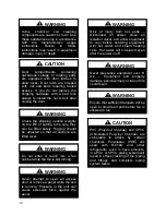
Страница 7: ...ould result in dangerous operation serious injury death or property damage Before servicing disconnect all electrical power to the unit More than one disconnect may be provided When servicing controls label all wires prior to disconnecting Reconnect wires correctly Verify proper operation after servicing Secure all doors with key lock or nut and bolt WARNING Electric shock hazard Before servicing ...

Страница 8: ...ing an Arc Flash Boundary to be field established and marked for identification of where appropriate Personal Protective Equipment PPE be worn should be followed WARNING UNIT HANDLING To prevent injury or death lifting equipment capacity shall exceed unit weight by an adequate safety factor Always test lift unit not more than 24 inches high to verify proper center of gravity lift point to avoid un...

Страница 9: ...n for leak testing A violent explosion may result causing injury or death WARNING Always use a pressure regulator valves and gauges to control incoming pressures when pressure testing a system Excessive pressure may cause line ruptures equipment damage or an explosion which may result in injury or death WARNING Do not work in a closed area where refrigerant or nitrogen gases may be leaking A suffi...

Страница 10: ... still turning WARNING Never attempt to open an access door or remove a panel while the unit is running Pressure in the unit can cause excessive force against the panel WARNING Never pressurize equipment over 8 w c Equipment and property damage personal injury or loss of life could result WARNING Ensure that sufficient dampers will be open to provide air path before fan is allowed to run WARNING R...

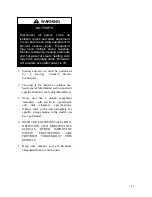
Страница 11: ... to the model you have purchased 4 READ THE ENTIRE INSTALLATION OPERATION AND MAINTENANCE MANUAL OTHER IMPORTANT SAFETY PRECAUTIONS ARE PROVIDED THROUGHOUT THIS MANUAL 5 Keep this manual and all literature safeguarded near or on the unit HOT PARTS Disconnect all power close all isolation valves and allow equipment to cool before servicing equipment to prevent serious injury Equipment may have mult...

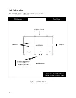
Страница 12: ... connections Figure 1 Unit Orientation Consider the air flow to be hitting the back of your head M3 Series Top View Return Air Supply Air Left Hand Side Right Hand Side Connections service access on left side for left hand orientation AIR FLOW Filter Coil Supply Fan ...

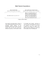
Страница 13: ... 00000 0 0 DPA 106 0 00 D0000 0000C M 0 Complete Model Number The complete unit model number consists of a base model number followed by a series of individual module numbers In the individual module model number the three numbers after the three letter Module ID indicate the position of the module in final air handling unit assembly increasing in value from the return outside air section to the d...

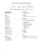
Страница 14: ...9 108 x 89 108 x 099 108 x 89 122 x 096 122 x 96 134 x 096 134 x 96 134 x 107 134 x 107 134 x 119 134 x 119 Voltage 2 230V 3Φ 60Hz 3 460V 3Φ 60Hz 4 575V 3Φ 60Hz 6 380 415V 3Φ 50Hz 8 208V 3Φ 60Hz Assembly A Factory Assembled B Shipping Splits Wiring 0 No Wiring A Wiring Motor Starters Branch Fusing Accessories 0 None A 115V Outlet Factory Wired 13Amp B 115V Outlet Field Wired 20 Amp Corrosion Prote...

Страница 15: ...4 Blowers with ODP Motors D 1 Blower with TEFC Motor E 2 Blowers with TEFC Motors F 3 Blowers with TEFC Motors G 4 Blowers with TEFC Motors Blower Type 0 Standard Efficiency A Premium Efficiency B Premium Eff with 1 VFD C Premium Eff with 1 VFD and Bypass D Premium Eff with Field Installed VFD E Premium Eff with 1 VFD Shipped Loose F Premium Eff with 2 VFDs G Premium Eff with 2 VFDs and Bypass H P...

Страница 16: ... 8 B 4 Pleated 30 Eff MERV 8 Filter Accessories 0 None A Clogged Filter Switch B Magnehelic Gauge C Options A B D Air Flow Measurement E Options A D F Options B D G Options A B D Power Switch 0 No Wiring A Power Block No Power Switch B 60 Amp Non fused Disconnect Switch C 100 Amp Non fused Disconnect Switch D 150 Amp Non fused Disconnect Switch E 250 Amp Non fused Disconnect Switch F 400 Amp Non f...

Страница 17: ... Options A D J Options B C K Options B D L Options C D P Options A B C Q Options A B D R Options A C D S Options B C D U Options A B C D Access 0 Left Door No Drain A Right Door No Drain B Both Doors No Drain C Left Door Left Drain D Left Door Right Drain E Left Door Both Drains F Right Door Left Drain G Right Door Right Drain H Right Door Both Drains J Both Doors Left Drain K Both Doors Right Dra...

Страница 18: ...ubes 50 50 Split C 4 Rows 5 8 Tubes 50 50 Split D 6 Rows 5 8 Tubes 50 50 Split E 8 Rows 5 8 Tubes 50 50 Split FPI 0 8 FPI 0 0060 Fin Thick 0 017 Tube Wall A 10 FPI 0 0060 Fin Thick 0 017 Tube Wall B 12 FPI 0 0060 Fin Thick 0 017 Tube Wall C 8 FPI 0 0075 Fin Thick 0 017 Tube Wall D 10 FPI 0 0075 Fin Thick 0 017 Tube Wall E 12 FPI 0 0075 Fin Thick 0 017 Tube Wall F 8 FPI 0 0100 Fin Thick 0 017 Tube ...

Страница 19: ...0 017 Tube Wall C 12 FPI 0 0060 Fin Thick 0 017 Tube Wall D 8 FPI 0 0075 Fin Thick 0 017 Tube Wall E 10 FPI 0 0075 Fin Thick 0 017 Tube Wall F 12 FPI 0 0075 Fin Thick 0 017 Tube Wall G 8 FPI 0 0100 Fin Thick 0 017 Tube Wall H 10 FPI 0 0100 Fin Thick 0 017 Tube Wall J 12 FPI 0 0100 Fin Thick 0 017 Tube Wall K 8 FPI 0 0060 Fin Thick 0 025 Tube Wall L 10 FPI 0 0060 Fin Thick 0 025 Tube Wall M 12 FPI ...

Страница 20: ...B Left Door Right Drain Left Coil Connections C Left Door Right Drain Right Coil Connections D Left Door Both Drains Left Coil Connections E Left Door Both Drains Right Coil Connections F Right Door Left Drain Left Coil Connections G Right Door Left Drain Right Coil Connections H Right Door Right Drain Left Coil Connections J Right Door Right Drain Right Coil Connections K Right Door Both Drains L...

Страница 21: ...Coil HCG Steam Coil with Internal Face and Bypass Dampers HCH Steam Coil with External Face and Bypass Dampers HCJ Integral Face and Bypass Steam Coil Position Level and Position of Module in Air Handling Unit Compartment Pressurization 0 Blow Through A Draw Through ELECTRIC HEAT Capacity 0 No Electric Heat A 40 kW B 80 kW C 120 kW D 160 kW E 200 kW F 240 kW G 280 kW H 320 kW J 360 kW K 400 kW L 4...

Страница 22: ...FPI 0 0060 Fin Thick 0 035 Tube Wall V 10 FPI 0 0060 Fin Thick 0 035 Tube Wall W 12 FPI 0 0060 Fin Thick 0 035 Tube Wall Y 8 FPI 0 0075 Fin Thick 0 035 Tube Wall Z 10 FPI 0 0075 Fin Thick 0 035 Tube Wall 1 12 FPI 0 0075 Fin Thick 0 035 Tube Wall 2 8 FPI 0 0100 Fin Thick 0 035 Tube Wall 3 10 FPI 0 0100 Fin Thick 0 035 Tube Wall 4 12 FPI 0 0100 Fin Thick 0 035 Tube Wall Type 0 No Heating Coil A Hot ...

Страница 23: ...None Blank 0 Standard Blank 0000 Standard Module Accessories 0 None A Treadplate Floor B Base Drain C Marine Light D Door Window F Options A B G Options A C H Options A D J Options B C K Options B D L Options C D P Options A B C Q Options A B D R Options A C D S Options B C D U Options A B C D Access 0 Left Door No Drain A Right Door No Drain B Both Doors No Drain C Left Door Left Drain D Left Doo...

Страница 24: ...r Bank Position Level and Position of Module in Air Handling Unit Blank 0 Standard Blank 00 Standard Pre filter 0 None A 2 Pleated 30 Eff MERV 8 B 4 Pleated 30 Eff MERV 8 Final Filter 0 None A 4 Cartridge Filter B 12 Cartridge Filter C 30 Bag Filter Final Filter Efficiency 0 None A MERV 11 65 Eff B MERV 13 85 Eff C MERV 14 95 Eff Accessories 0 None A Clogged Filter Switch B Magnehelic Gauge C Opti...

Страница 25: ...eft D Right E Top F End Dampers G Bottom Dampers H Left Dampers J Right Dampers K Top Dampers Return Air Location 0 None A End B Bottom C Left D Right E Top F End Dampers G Bottom Dampers H Left Dampers J Right Dampers K Top Dampers Exhaust Air Location 0 None A End B Bottom C Left D Right E Top F End Dampers G Bottom Dampers H Left Dampers J Right Dampers K Top Dampers L End Barometric Relief Dam...

Страница 26: ...ht Doors No Drain C Left Door Left Drain D Left Door Right Drain E Left Door Both Drains F Right Door Left Drain G Right Door Right Drain H Right Door Both Drains J Left and Right Doors Left Drain K Left and Right Doors Right Drain L Left and Right Doors Both Drains M Left and End Doors No Drain N Left and End Doors Left Drain P Left and End Doors Right Drain Q Left and End Doors Both Drains R Rig...

Страница 27: ...ampers G Left Dampers H Right Dampers J Top Dampers Damper Actuator Type 0 None A Standard Damper B Standard Damper On Off Actuator C Standard Damper 0 10 VDC Actuator Opening Accessories 0 None A Burglar Bars Blank 0 Standard Power Switch 0 No Wiring A Power Block No Power Switch B 60 Amp Non fused Disconnect Switch C 100 Amp Non fused Disconnect Switch D 150 Amp Non fused Disconnect Switch E 250...

Страница 28: ...ss 0 Left Door No Drain A Right Door No Drain B Both Doors No Drain C Left Door Left Drain D Left Door Right Drain E Left Door Both Drains F Right Door Left Drain G Right Door Right Drain H Right Door Both Drains J Both Doors Left Drain K Both Doors Right Drain L Both Doors Both Drains M No Door No Drain Type 0 Standard A Stainless Steel Interior B Stainless Steel Exterior C Options A B X Special ...

Страница 29: ...nect Switch C 100 Amp Non fused Disconnect Switch D 150 Amp Non fused Disconnect Switch E 250 Amp Non fused Disconnect Switch F 400 Amp Non fused Disconnect Switch G 600 Amp Non fused Disconnect Switch H 60 Amp Fused Disconnect Switch J 100 Amp Fused Disconnect Switch K 150 Amp Fused Disconnect Switch L 250 Amp Fused Disconnect Switch M 400 Amp Fused Disconnect Switch N 600 Amp Fused Disconnect Sw...

Страница 30: ...s G 4 Blowers with TEFC Motors Blower Type 0 Standard Efficiency A Premium Efficiency B Premium Eff with 1 VFD C Premium Eff with 1 VFD and Bypass D Premium Eff with Field Installed VFD E Premium Eff with 1 VFD Shipped Loose F Premium Eff with 2 VFDs G Premium Eff with 2 VFDs and Bypass H Premium Eff with 2 Field Installed VFDs J Premium Eff with 2 VFDs Shipped Loose K Premium Eff with 3 VFDs L Pr...

Страница 31: ...RV 8 B 4 Pleated 30 Eff MERV 8 C Option A Clogged Filter Switch D Option B Clogged Filter Switch E Option A Magnehelic Gauge F Option B Magnehelic Gauge G Option A Clogged Filter Switch Magnehelic Gauge H Option B Clogged Filter Switch Magnehelic Gauge Outside Air Location 0 None A End B Left C Right D Left and Right E Top F End Dampers G Left Dampers H Right Dampers J Left and Right Dampers K Top...

Страница 32: ...ptions A C H Options A D J Options B C K Options B D L Options C D P Options A B C Q Options A B D R Options A C D S Options B C D U Options A B C D Access 0 Left Door No Drain A Right Door No Drain B Both Doors No Drain C Left Door Left Drain D Left Door Right Drain E Left Door Both Drains F Right Door Left Drain G Right Door Right Drain H Right Door Both Drains J Both Doors Left Drain K Both Doo...

Страница 33: ... Pleated 30 Eff MERV 8 C Option A Clogged Filter Switch D Option B Clogged Filter Switch E Option A Magnehelic Gauge F Option B Magnehelic Gauge G Option A Clogged Filter Switch Magnehelic Gauge H Option B Clogged Filter Switch Magnehelic Gauge Return Air Opening Location 0 None A Bottom B Left C Right D Bottom Dampers E Left Dampers F Right Dampers G Bottom Burglar Bars H Left Burglar Bars J Bott...

Страница 34: ...ess 0 Left Door Left Drain 1 Left Door No Drain 2 Right Door No Drain 3 Both Doors No Drain B Left Door Right Drain D Left Door Both Drains F Right Door Left Drain H Right Door Right Drain K Right Door Both Drain M Both Doors Left Drain P Both Doors Right Drain R Both Doors Both Drains Type 0 Standard A Stainless Steel Interior B Stainless Steel Exterior C Options A B X Special Pricing Authorizati...

Страница 35: ...emium Eff with 2 VFDs Shipped Loose K Premium Eff with 3 VFDs L Premium Eff with 3 VFDs and Bypass M Premium Eff with 3 Field Installed VFDs N Premium Eff with 3 VFDs Shipped Loose P Premium Eff with 4 VFDs Q Premium Eff with 4 VFDs and Bypass R Premium Eff with 4 Field Installed VFDs S Premium Eff with 4 VFDs Shipped Loose Blower HP 0 1 hp 1170 rpm A 2 hp 1170 rpm B 3 hp 1170 rpm C 5 hp 1170 rpm ...

Страница 36: ...all Module Accessories 0 None A Treadplate Floor B Base Drain C Marine Light D Door Window F Options A B G Options A C H Options A D J Options B C K Options B D L Options C D P Options A B C Q Options A B D R Options A C D S Options B C D U Options A B C D Access M No Door No Drain N No Door Left Drain P No Door Right Drain Q No Door Both Drains Type 0 Standard A Stainless Steel Interior B Stainle...

Страница 37: ...ight carrier is in compliance with Bill of Lading instructions 2 Inspect delivery before signing Bill of Lading If damage is found or items are missing 1 Note on Bill of Lading immediately 2 Call carrier immediately to file a freight claim and to schedule an inspection 3 Photograph damage if possible 4 Do not move or discard damaged freight packaging materials 5 After losses have been acknowledged...

Страница 38: ...kable Handle The warranty card must be completed in full and returned to AAON not more than 3 months after unit is delivered Storage Indoor units are not designed for outdoor use or storage Equipment should be protected from environmental conditions such as rain snow humidity extreme temperatures and corrosive chemicals If installation will not occur immediately following delivery then store the e...

Страница 39: ... connected to one spreader bar and the straps chains or cables connected to a single spreader bar should be the same length The angle of each strap should be a minimum of 60 from horizontal to prevent excess lateral force on the lifting points All shipping covers should be left in place until ductwork is ready to be connected or shipping sections are ready to be joined Figure 4 Unit Lifting Side V...

Страница 40: ...will also be displayed on each module so that each module can be reattached to the correct unit Figure 5 Module Location Example Module Assembly The following tools are suggested for equipment assembly Power drill with 5 16 socket Come along 2 wrench and socket Crowbar Phillips head screwdriver 1 Move the section chosen to be installed first to the correct position It is recommended to start with ...

Страница 41: ...ick low durometer neoprene Figure 7 Neoprene Gasket 3 Correctly orient the second section and move it close to the first while aligning the two sections The split unit lifting lugs should be removed once there is no longer a need to lift the section Figure 8 Module Connection 4 Pull the two sections together using a come along attached to the lifting points on the base rail Figure 9 Module Connect...

Страница 42: ...igned by using a come along diagonally across the top of the unit Figure 12 Aligning the Top of a Unit 5 Secure the two sections together with bolts in the holes surrounding the lifting hole in the base rail Be sure to replace the lifting lugs on either side of the two base rails before bolting together Figure 13 Lifting Lugs and Bolts 6 Pull the top of the two sections together using a come along...

Страница 43: ...sten sections together with self tapping screws 10 HEX HEAD on top angle Figure 16 Fastening Sections Together 9 Attach integrated splice on walls and roof to adjoining section with self tapping screws 10 HEX HEAD Figure 17 Attaching Splice 10 Attach corner rail cover with provided 5 10 flat head screws Figure 18 Attaching Corner Rail Cover ...

Страница 44: ...bling sections be sure that all gaskets are in place It is the contractor s responsibility to seal all field split sections Spring Isolator Adjustment AAON M3 Series air handling units are equipped with spring isolators in all blower sections for vibration attenuation Prior to unit shipment the isolators are set in the lock down position and the blower section deck is resting on a wood base to pro...

Страница 45: ...ctory for field installation The related photos of the wheel are provided for practical guidelines only in order to identify the air band location in the wheel Actual field installation of the air band into the wheel will require access into and through the blower wheel venturi The band is made of aluminum sized and equipped with easy bend tabs that are to be inserted into pre punched slots provid...

Страница 46: ...ough the condensate drain piping Blow through coils will have a positive static pressure in the drain pan The condensate piping on these drain pans must be trapped to prevent pressure loss through the drain Condensate drain trapping and piping should conform to all applicable governing codes Note The drain pan connection is a 1 5 MPT fitting Condensate drains that are not properly trapped could ca...

Страница 47: ...bend of the trap to the bottom of the leaving pipe must be at least equal to one half of the X dimension This ensures that enough water is stored in the trap to prevent losing the drain seal during unit startup Note The absolute value of the fan inlet pressure will always be greater than or equal to the absolute value of the static pressure in the drain pan on draw through units so the fan inlet p...

Страница 48: ...ing the largest negative static pressure entering the unit and then subtracting any pressure drops between that point and the drain pan In the case below the outside air static pressure is 0 75 due to duct loss between the unit and the outside air intake The return air static pressure is 1 5 due to the building pressure and duct loss between the space and the unit In this case the 1 5 would be use...

Страница 49: ... static pressure at the return air opening These values are listed on the Unit Rating Sheet which can be obtained from the AAON sales representative Figure 25 Example Draw Through AAONEcat32 Rating Sheet ...

Страница 50: ...n of the draw through p trap should be at least 4 32 which is the absolute value of the calculated static pressure in the drain pan plus one inch The lower part of the p trap should be half that value or 2 16 The total height of the p trap would be 6 48 measured from the bottom of the drain pan connection to the top of the bottom bend so one diameter of the pipe needs to be added to find the requi...

Страница 51: ...inimum pressure drop so do not include dirt allowance pressure drops for filters The bottom of the leaving pipe should be at least one half inch lower than the bottom of the drain pan connection This ensures proper drainage when the unit is not running Note It may be necessary to fill the trap manually or the trap can be filled automatically by operating the unit until enough condensate collects t...

Страница 52: ...een the drain pan and the supply air ductwork are the discharge opening and the heating coil To find the static pressure in the drain pan subtract 08 and 15 from the 3 supply air external static pressure This gives a positive pressure in the drain pan of 2 77 These values are listed on the Unit Rating Sheet which can be obtained from the AAON sales representative ...

Страница 53: ...53 Figure 28 Example Blow Through AAONEcat32 Rating Sheet ...

Страница 54: ...e following procedure 1 Remove the external control panel from the shipping position in the supply fan module 2 Install the external control panel by placing it on the preinstalled mounting bracket on the exterior of the supply fan module 3 While one or two people hold the external control panel in place on top of the mounting bracket another person should secure it to the wall of the unit with se...

Страница 55: ...ard C22 1 Canadian Electric Code Part 1 For field wired units refer to the motor connection diagram on the inside of the motor terminal box for wiring instructions Check the electrical characteristics of the motor to make sure they correspond to the supply voltage and the conductor size used Foam Insulated Panel Cutting Note The location for field cut electrical entry is marked on the unit Field c...

Страница 56: ...d corners that are not covered should then be sealed using silicone caulking or a duct seal compound If a reciprocating saw is used to make the cut out take care that the metal skins of the foam part do not separate from the foam this would result in reduced structural integrity of the part Dampers and Actuators AAON damper blades are connected with interlocking gears A coupling is attached to one...

Страница 57: ...onnections The connecting piping should never be supported by the coil it should be independently supported Swing joints or flexible fittings should be used to absorb expansion and contraction due to temperature changes An access cover is provided for the chilled water hot water and steam coil vent and PVC Polyvinyl Chloride and CPVC Chlorinated Polyvinyl Chloride are vulnerable to attack by certa...

Страница 58: ...accessories and all control sequences Have appropriate literature on hand for consultation Startup Checklist Check all electrical connections for tightness Inspect all sections Remove any shipping restraints and check for loose debris Check fan set screws for tightness turn fan to assure free rotation Ensure electrical supply matches unit nameplate Ensure condensate lines are connected glued and s...

Страница 59: ...e that the dampers are operating such that airflow through the unit will not be shut off while the fan is operating This could cause severe damage to the unit 5 Check the operation of all water valves Simulate calls for cooling and heating check for the proper response of the valves Check the operation of any other optional equipment per the manufacturer s specifications Commissioning The commissi...

Страница 60: ...nd valves Correct unusual cycling Check for correct damper operation Check blower set screws Tighten if necessary Monthly Check filters for cleanliness Replace if necessary Check drain pans to ensure proper drainage and clean as necessary Inspect all coils Clean if dirty or obstructed in any way Seasonal Check operation of heating and cooling sequences Check for correct damper operation Check fans...

Страница 61: ... over if the tool is applied across the fins Use of a water stream such as a garden hose against a surface loaded coil will drive the fibers and dirt into the coil This will make cleaning efforts more difficult Surface loaded fibers must be completely removed prior to using low velocity clean water rinse A monthly clean water rinse is recommended for coils that are applied in coastal or industrial...

Страница 62: ... with no areas missed This may be accomplished by use of a pump up sprayer or conventional spray gun The method does not matter as long as the entire area to be cleaned is wetted After the substrate has been thoroughly wetted the salts will be soluble and is now only necessary to rinse them off Rinse It is highly recommended that a hose be used as a pressure washer will damage the fins The water t...

Страница 63: ...ownstream side of the coil this should center the coil in the opening Push the coil all the way in so that the return bend side of the coil is between 1 8 and 1 4 from the inside wall of the unit For cooling coils be sure that the vertical headers are entirely over the drain pan Screw the coil end panel to the coil using self tapping sheet metal screws Figure 35 Coil Removal Doors Panels Removable...

Страница 64: ... gasket needs to be applied on the door jamb of the new door side The door latch parts will need to be removed and replaced on the new door side Filters Pleated filters install from upstream side of filter rack Filters are installed in columns For each column open snap fasteners and remove first filter Slide the rest of the filters to the opening and then remove Bag and cartridge filters are insta...

Страница 65: ... number and part number when ordering parts AAON Warranty Service and Parts Department 2424 S Yukon Ave Tulsa OK 74107 Ph 918 583 2266 Fax 918 382 6364 www aaon com Note Before calling technician should have model and serial number of the unit available for the service department to help answer questions regarding the unit ...

Страница 66: ...4 44 ft2 039 20 x 16 5 5 25 55 56 ft2 045 24 x 20 5 4 20 66 67 ft2 054 20 x 16 6 5 30 66 67 ft2 060 20 x 16 6 6 36 80 00 ft2 067 20 x 16 7 6 42 93 33 ft2 074 25 x 16 6 6 36 100 00 ft2 083 25 x 20 6 5 30 104 17 ft2 094 25 x 16 6 7 42 116 67 ft2 Table 5 Cartridge Bag Filters Unit Size Primary Filter Size Quantity Secondary Filter Size Quantity Face Area 032 20 x 20 12 12 x 24 2 37 33 ft2 039 20 x 24...

Страница 67: ...67 Figure 38 Cartridge Bag Filter Layout Viewed from Upstream Side Filters Face Load Into Type 8 Holding Frame ...

Страница 68: ... Yes No 3 Are the unit clearances adequate for service and operation Yes No 4 Do all access doors open freely and are the handles operational Yes No 5 Have all shipping braces been removed Yes No 6 Have all electrical connections been tested for tightness Yes No 7 Does the electrical service correspond to the unit nameplate Yes No 8 On 208 230V units has transformer tap been checked Yes No 9 Has o...

Страница 69: ...bly Wheels Spin Freely Check Rotation FLA ________ Number hp L1 L2 L3 1 2 Power Exhaust Fan Assembly Alignment Check Rotation Nameplate Amps________ Number hp L1 L2 L3 1 2 Band Size_____________________ VFD Frequency________________ Springs Operating Correctly Power Return Fan Assembly Alignment Check Rotation Nameplate Amps________ Number hp L1 L2 L3 1 2 Band Size_____________________ VFD Frequen...

Страница 70: ... Operation Check Damper Wiring Check Gears Check Damper Actuator Type __________________________________________________________ Economizer Changeover Type and Operation _______________________________________ Electric Heating Stages__________ Limit Lockout Aux Limit Lockout Door Interlock Stage Amps Stage Amps 1 7 2 8 3 9 4 10 5 11 6 12 ...

Страница 71: ...ocument any service repair or adjustments AAON Service and Warranty Departments are available to advise and provide phone help for proper operation and replacement parts The responsibility for proper startup maintenance and servicing of the equipment falls to the owner and qualified licensed technician Entry Date Action Taken Name Tel ...

Страница 72: ... filter from MERV 7 to MERV 8 correcting the Unit Lifting Drawing to show a 60 degree minimum strap angle adding the electronic startup form adding the index of tables and figures and updating the table of contents March 2014 Updated factory trained service technician text and feature string nomenclature July 2015 Added Features and Options Introduction August 2016 Added E coated cleaning section ...

Страница 73: ...73 ...

Страница 74: ...74 ...

Страница 75: ...75 ...

Страница 76: ...s the intent of AAON to provide accurate and current product information However in the interest of product improvement AAON reserves the right to change pricing specifications and or design of its product without notice obligation or liability Copyright AAON all rights reserved throughout the world AAON and AAONAIRE are registered trademarks of AAON Inc Tulsa OK ...

Отзывы: