


If you have to attach brackets or fasteners to the
AHU panels or frame, use only those specially
approved for your AHU as otherwise there is a risk of
leakages.
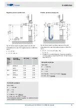
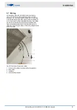
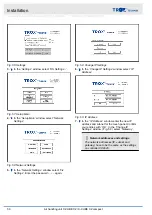
Fig. 31: Exemplary illustration of the heat exchanger
connections in a counter flow arrangement
1
Airflow direction
Stickers on the connection side of the heat
exchangers indicate the flow ( Fig. 31 /IN) and return
connections ( Fig. 31 /OUT) for a counter flow
arrangement.
In special constructions of the heat exchanger, these
stickers may not show the correct type of connection.
The heat exchangers must always be connected in a
counter flow arrangement. For questions on the con-
nections, please contact the unit manufacturer.
Connect slide-out heat exchangers and droplet elimina-
tors with bends and detachable connections as other-
wise you will not be able to withdraw them.
Personnel:
HVAC technician
Protective equipment:
Industrial safety helmet
Hearing protection
Protective clothing
Protective gloves
Safety shoes
NOTICE!
Risk of damage to property from incorrect pipe
connections!
Take care to connect the heat exchanger pipes cor-
rectly as otherwise the pipes may twist or become
subject to adverse effects. This may eventually
damage the heat exchanger beyond repair.
–
Connect pipes in such a way that the heat
exchanger is not affected by vibration and that
no loads are imposed on it.
–
If there is too much weight on a water pipe (by
others), support the water pipe.
–
Do not use the connection point of the heat
exchanger as a fixing point for other parts.
–
When you tighten thread connections, be sure to
use a suitable tool (e.g. water pump pliers) to
counter the tightening force as otherwise you
may inadvertently damage the parts.
–
If an AHU is installed outdoors, use suitable
pipes and protect them from frost.
–
Ensure that no air gets trapped in the pipes.
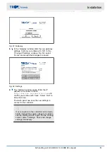
Fig. 32: Using water pump pliers to counter the tight-
ening force
1.
Hold the threaded pipe tail of the heat exchanger
with water pump pliers ( Fig. 32 /2).
2.
Hold the threaded pipe tail with the pliers while
you use a spanner (hexagonal profile, Fig. 32 /1)
to connect the heat exchanger to the pipework
(pipework by others).
Installation
Connecting the heating coil/cooling coil
Air handling unit X-CUBE X2 / X-CUBE X2 compact
37
Содержание X-CUBE X2
Страница 69: ...Appendix Appendix Air handling unit X CUBE X2 X CUBE X2 compact 69...
Страница 71: ...A Adjusting the storage mass Adjusting the storage mass Air handling unit X CUBE X2 X CUBE X2 compact 71...
Страница 72: ...Montageanleitung Mounting Instructions KLINGENBURG Ausrichtung der Speichermasse Adjustment of storage mass...


