


!
WARNING
Remove the baffles if there are any signs of condensation in the
chimney or chimney connector. Removing baffles may not ad-
dress condensation.
!
DANGER
The chimney and connector shall be inspected annually for signs
of debris and corrosion. Loose mortar at the base of the chimney
may be a sign of condensate damage to the chimney. A chimney
professional shall be contacted immediately to examine the dam-
age and recommend a solution. Long term operation while in this
condition may cause a venting failure and force flue gases into
the living space. If the chimney is to be re-lined, use the recom-
mendations in NFPA31, Appendix E or CSA B139.
!
DANGER
Any signs of condensate seepage at the base of the chimney shall
be inspected immediately. The discoloration may be a sign of
chimney damage and must be remedied immediately.
38
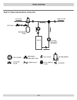
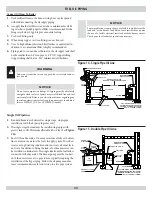
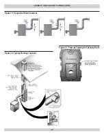
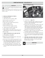
VeNT PiPe
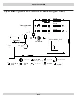
A Vent pipe is used to connect the boiler to the chimney. The
1.
vent pipe should be kept as short as possible. The horizontal
length of the vent pipe should not be greater than 10 feet.
Type L Vent pipe – a type L vent or other suitable material shall
2.
be used for a vent pipe if the flue temperature is less than 570°
F.
Attach vent pipe and flue adaptor ring with three screws. Pre-
3.
drill cast iron flue collar to prevent cracking.
The 4,5 & 6 section boilers have a sheet metal flue collar spacer
4.
included in the accessory carton.
Canadian versions have a vent spill switch kit included.
5.
DrAFT
The natural draft generated through a chimney is dependent on
1.
several factors including, chimney height, temperature of flue
gases, cross section area of chimney, chimney wall insulation
value, dilution air and total volume of flue gases. Make sure
that the boiler has been running for at least 5 minutes before
measuring the draft.
Minimum Draft at Breech – The draft induced by a chimney
2.
must create at least a pressure of 0 (zero) inches water column
(INWC) at the breach. The pressure at the breach cannot be
positive since this could create a condition that allows flue gas
by-products to escape from the draft regulator. Draft is to be
measured up stream of the draft regulator. (See the Burner
Specifications section at the rear of this manual for more de-
tails.)
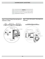
CHiMNeY AND CHiMNeY CONNeCTiONS
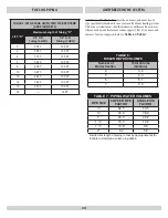
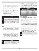
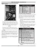
Overfire pressure- Measure pressure in 1/4”NPT test port. The
3.
3-pass boilers have higher pressure drop then a single pass.
Table 8A shows the expected pressure drop between the overfire
and breech. Add together. (IE draft= -0.05 INWC breech = 0.05,
total pressure drop = 0.10 INWC) See
Figure #21
.
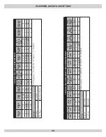
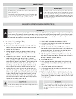
Table 8A:
Pressure drop between overfire & breech
Sections
Baffle In
Baffle Out
4
0.03-0.05
0.03-0.05
5
0.05-0.08
0.05-0.08
6
0.09-0.16
0.09-0.16
7
N/A
0.07-0.16
STACK TeMPerATUre
The higher the stack temperature, the greater the amount of
4.
draft that can be generated. A lower stack temperature not
only reduces the amount of draft that can be created but it also
increases the possibility that the flue gases could condense in
the chimney connector or stack.
NFPA 31 and CSA B139 have information to help the installer
5.
make an appropriate choice of venting materials. In some
cases, a chimney may have to be lined to create sufficient draft.
In other cases, the chimney may have to be lined to prevent the
corrosion of a masonry chimney. Consult with a chimney spe-
cialist knowledgeable on the requirements for chimney require-
ments in your area.
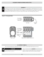
Baffles – The efficiency of the boiler is based on the insertion
6.
of flue baffles supplied with 4,5 & 6 section units. The baffles
are installed in the 3rd pass (two inner flueways). Refer to the
ASSEMBLING THE BOILER section for baffle installation.
Remove the baffles to increase the stack temperature.


