


!
WARNING
Under no circumstances can copper with sweat style connec-
tors be used
NOTICE
Do not use compression fittings. Oil piping must be absolutely
air tight or leaks or loss of prime may result. Bleed line and fuel
unit completely. Refer to your local jurisdictions regarding any
special considerations for fuel supply requirements. In addition,
refer to NFPA 31 (U.S.) or CSA B139 (Canada)
NOTICE
Some jurisdictions require the use of a fusible shutoff valve at the
tank and/or the burner. In addition, some jurisdictions require
the use of a fusible electrical interlock with the burner circuit.
Check your local codes for special requirements.
33
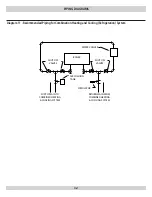
Connect Oil Lines To Boiler
Use flexible oil lines so the burner swing door can be opened
1.
without disconnecting the oil supply piping.
A supply line fuel oil filter is required as a minimum for all fir-
2.
ing rates but a pleated paper fuel filter is recommended for the
firing rates below 1.0 gph to prevent nozzle fouling.
Use flared fittings only.
3.
When using copper, cast iron fittings cannot be used.
4.
Use of a high efficiency micron filter (Garber or equivalent) in
5.
addition to a conventional filter is highly recommended.
Piping used to connect the oil burner to the oil supply tank shall
6.
not be smaller than 3/8” iron pipe or 3/8” OD copper tubing.
Copper tubing shall have a .032” minimum wall thickness.
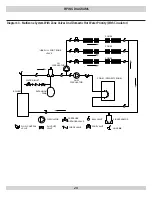
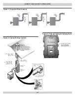
Single Oil Pipelines
Standard burners are delivered as single-stage , single pipe
1.
installation (with the bypass plug removed.)
The single-stage fuel unit may be installed single-pipe with
2.
gravity feed or lift. Maximum allowable lift is 8 feet. See
Figure
#14
.
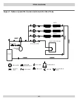
Fuel Oil Line Deaerator- On many occasions a leaky oil delivery
3.
line can introduce air into the fuel oil supply system. This often
creates a rough starting condition and can create a burner lock-
out state. In addition to fixing the leak, a fuel line deaerator can
be installed to eliminate air. The single line from the fuel tank is
connected to the deaerator. The burner pump must be connect-
ed to the deaerator as a two pipe system, typically requiring the
installation of the bypass plug. Follow the oil pump manufac-
turer’s recommendations for conversion to a two pipe system.
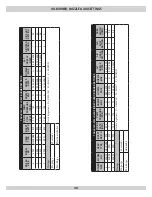
FUeL OiL PiPiNg
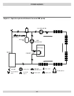
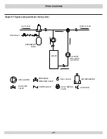
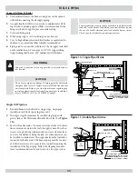
TYPICAL INSTALLATION
TWO PIPE OIL SYSTEM
BOILER
BAROMETRIC
DRAFT CONTROL
OIL LINE MUST BE BURIED OR
OTHERWISE PROTECTED FROM
DAMAGE. MINIMUM 1/2" IPS OR
OIL FILTER
SHUT OFF VALVE
JOINTS
APPROVED
FITTINGS
SUCTION
FILL
PIPE
1/2" O.D. COPPER TUBING
OIL
SWING
RETURN LINE
REFER TO LOCAL
CODE
CHECK
VALVE
LINE
*
TANK
OIL BURNER
UTICA
BOILERS
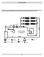
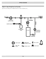
TYPICAL INSTALLATION
SINGLE PIPE OIL SYSTEM
BOILER
BAROMETRIC
DRAFT CONTROL
OIL LINE MUST BE BURIED OR
OTHERWISE PROTECTED FROM
DAMAGE. MINIMUM 3/8" IPS OR
APPROVED FITTINGS
3/8" O.D. COPPER TUBING
OIL BURNER
SWING JOINTS
OIL TANK
OIL FILTER
SHUT OFF VALVE
REFER TO NATIONAL
BOARD OF FIRE UNDERWRITERS
VENT PIPE
OIL GAUGE
FILLER
PIPE
MINIMUM
UTICA
BOILERS
Figure 14 - Single Pipe Oil Line
Figure 15 - Double Pipe Oil Line


