


13
Remove Crate
1.
Remove all fasteners at crate skid.
A.
Lift outside container and remove all other inside protective
B.
spacers and bracing. Remove burner and miscellaneous parts
boxes.
Remove Boiler from skid
2.
. Boiler is secured to base with 4
screws. Remove all securing hardware.
Move boiler into permanent position by sliding or walk-
3.
ing into place.
!
CAUTION
Do not drop boiler. Do not bump boiler jacket against floor.
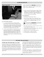
Open the burner swing door
4.
. Throughout this manual, you
will be instructed to open and close the burner swing door for vari-
ous reasons. There is a proper and improper method to closing and
securing the burner swing door opened for inspection, cleaning or
field service.
Loosen and remove non-hinged side latching hardware.
A.
Remove hinged side latching hardware.
B.
Door can be swung to the fully open position, approximately.
C.
90 to 120 degrees, with the burner mounted providing that
there is 22” of clearance to the adjacent wall.
!
CAUTION
If burner door is lifted when opened, it can come off it’s hinges.
NOTICE
If reduced clearance prevents the door from opening fully, one
of the following can provide full access:
Burner can be removed to allow full rotation of door.
Door with burner mounted can be lifted off hinges and set aside
during servicing.
The door mounting hardware is reversible from left side hinge (as
shipped) to right side hinge. To reverse the hinge arrangement:
(See Figure #2C)
Lift door off mounting eye bolts and set aside.
Remove mounting eye bolts from left side.
Move door mounting eye bolts to right side.
Tighten both sets of hardware.
Lift door and place integral cast hinge pins on door into slotted
mounting bracket holes.
Inspect Swing door insulation and rope gasket.
5.
Inspect fiber rope located on the swing door. The rope must
A.
be evenly distributed around the perimeter of the door groove
and cannot bunch or overhang. There must not be a gap where
the two ends of the rope meet. Repair or replace if the rope is
damaged or if there is a gap between the ends.
Inspect burner swing door insulation for damage.
B.
By design, the combustion chamber and raised portion be-
C.
tween the 2nd and 3rd pass flue ways should make an impres-
sion in door insulation.
Do not close and secure door at this time.
D.
Figure 2C - reversible Hinge
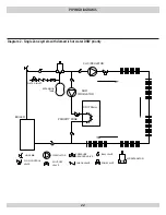
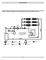
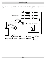
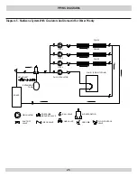
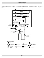
NOTICE
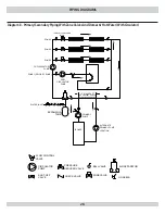
For the purpose of these instructions, all pipe connections shall
use pipe dope or Teflon tape to assure water tight connections
unless otherwise instructed. For steps 6 thru 16, refer to Figure
#6.
Open accessory carton
6.
and remove contents. Identify the
components using the illustrations throughout this section as
applicable to your installation.
Remove top panel
7.
. Remove sheet metal screws securing the top
panel to jacket rear panel. Slightly lift rear of jacket top panel away
from side panels. If the boiler is equipped with a lifting hinged
front panel, push the top panel toward the rear of the boiler and
lift off of side panels to gain access to internal control panel.
Locate the shorter of the two 1 1/4” nipples
8.
. Thread thru
the insulation slot into supply port in rear of boiler. Locate the 1
1/4” x 90° elbow and assemble onto nipple. Be sure connections
are
tight
and outlet is facing directly up. See
Figure #3
.
Locate the longer of the two 1 1/4” nipples
9.
. Assemble onto
elbow. See
Figure #3
.
ASSeMBLiNg THe BOiLer
NOTICE
It is recommended that hinges should be on same side as flexible
oil line in order to swing the door open.


