


19
eqUiPMeNT AND ACCeSSOrieS
DiAPHrAgM eXPANSiON TANK (not provided)
The diaphragm type expansion tank takes the place of the conven-
tional expansion tank. Carefully read the instructions packed with
your tank assembly. The expansion tank should be sized and installed
correctly. An improperly installed or sized expansion tank may result
in frequent lifting of the relief valve or other heating system problems.
The tank typically comes with a 10-12 psig air charge. This is the same
as the pressure produced in the system by an automatic fill valve set
to fill the boiler to 10-12 psig with fresh water. When the system is
first filled, the tank will fill partially with water. As the water is heated,
and system pressure increases, the water expands into the tank and
compresses the air in the tank. This compressed air cushion permits
the water in the system to expand as the temperature changes and
assures a “full measure” of water, even in the highest radiation unit of
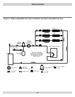
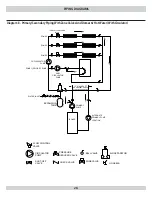
the system. The diaphragm type expansion tank can be mounted on
the air purger fitting or at any other convenient place in the supply or
return line. It is recommended to locate the diaphragm type expansion
tank in the supply line with the circulator located after the expansion
tank. This configuration allows the circulator to “pump away” from
the expansion tank for improved air elimination and system perfor-
mance. The air eliminator fitting or air purger is not provided. The air
eliminator fitting or air purger is used to help remove air from the sys-
tem before it reaches the radiators. It should be installed in the supply
line. Air left in the system can cause noises in the pipes and inefficient
circulation in the radiators.
MAiN Air VeNT: (not provided)
Before a system is filled with water, there is air in the pipes and
radiation units. Some of the air will be trapped as the system is filled.
It is possible to eliminate most of this air through the air vents on the
radiation units. A main air vent will speed and simplify this process.
The main air vent should be installed on the highest point in the sup-
ply main.
AUTOMATiC FiLL VALVe (not provided)
For safe, efficient operation, a hot water system must be filled with
water. Adding new water, when needed can be done manually (by
use of a hand valve in the water supply line). This requires regular
attention to the system’s needs. An automatic fill valve or pressure
reducing valve accomplishes this without attention. It is installed in
the supply line on hot water boilers only. The valve operates through
water pressure differentials. It does not require an electrical connec-
tion.
AqUASTAT reLAY CONTrOL (provided)
The water temperature limit control in the aquastat relay is adjust-
able. See Aquastat instructions for how to set the limit temperature.
DrAiN VALVe (provided)
The drain valve is a manually operated valve that provides a means
of draining all the water from the boiler and heating system. It is
installed in the casting below the burner door.
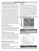
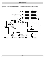
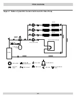
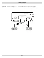
CirCULATOr
Every forced hot water system requires a circulator. A separate
circulator or zone valve is required for each zone, if there are two
or more zones. The circulator must have the capacity to provide the
circulation required by the heating system. The circulator should be
connected to the supply main and must be wired into the boiler’s
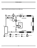
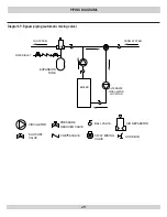
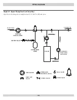
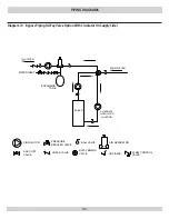
electrical system. See the “System Piping” section for piping configu-
rations with the circulator located on the supply main piping using
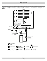
zone circulators or zone valves. When the piping is arranged with
zone circulators and no bypass piping, the circulator provided with
the boiler may be used as a zone circulator. Both piping arrange-
ments allow the circulator to pump away from the expansion tank
and show how the piping should be arranged to allow the heating
system to be easily purged of air. The circulator can be installed on
the return side of the boiler, if preferred.
15
10
5
0
5
4
3
2
1
m H
ead
1
2
3
4 5
US GPM
5
10
15 20
m /h
3
H
ead (f
eet)
Model
Watts
Volts Amps
Capacitor
UP 15-42F
85
115
0.74
10µF/180V*
*Supplied with pump
Figure 13A - grundfos Pump Curve
Model
Volts Amps
Capacitor
007-F5
115
0.70
Supplied w/ pump
Figure 13B - Taco Pump Curve


