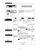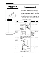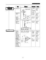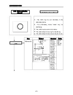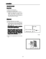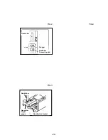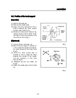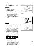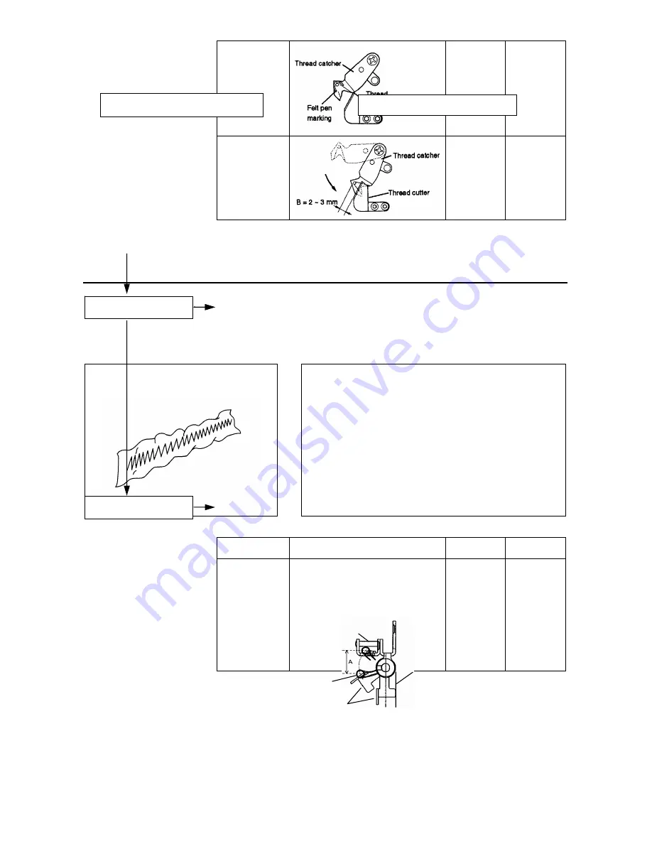
Thread
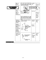
cutter
evenness
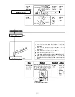
Smear the
thread
catcher with
a felt pen,
and check if
the thread
cutter makes
contact
evenly.
Must be
contact
evenly.
Adjust.
See
P.25.
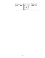
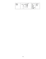
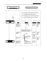
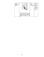
Blade
pressure
B=2
~
3mm
(0.6
~
1.5kg・
㎝)
Adjust.
See
P.25.
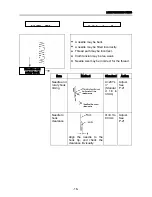
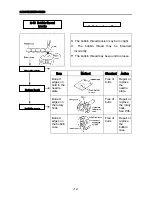
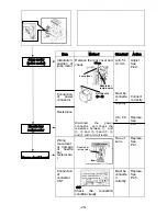
2.TROUBLESHOOTING
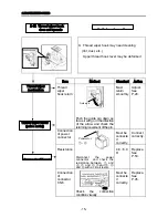
・ The needle or bobbin thread tension may be
too tight.
・ The needle and thread may be too thick for
the cloth.
・ The cloth tension may be too loose.
・ The needle tip may be blunt.
・ The hole in the needle plate may be burred.
・ The needle thread may be stuck around the
threading tube holder and the thread take-up
lever.
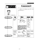
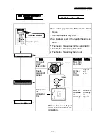
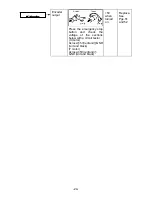
Item
Method
Standard Action
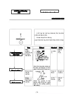
Thread take
-up spring
stroke (A)
Hold the thread before the needle
roller. Pull the thread downward and
the thread take-up spring starts
moving. Check the length of thread
pulled until the spring stops.
A=20±
1mm
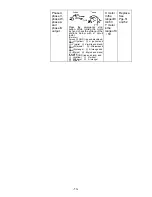
Move the
retracting
lever
position
up and
down to
adjust.
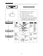
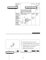
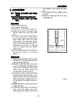
Lower cover
Retracting Lever
(Equivalent to 8 teeth of ratchet)
Needle Roller
Thread Take-up
Spring
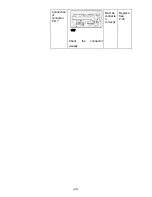
Thread tension
Thread tension
Hook support
Preliminary inspection
2-14 Puckering
-17-
Содержание ESP9000
Страница 1: ...SERVICE MANUAL Embroidery Machine ESP9000 15 needles...
Страница 2: ......
Страница 13: ...FIG 3 48...
Страница 24: ...FIG 4 59...
Страница 26: ...22 Power supply and consumption 100 120 200 240VAC 50 60Hz 220W 23 Dimensions 835 H x 745 W x 740 D 2...
Страница 36: ...Connection of connector CN 10 Must be connected correctly Replace See P 47 CN10 11...
Страница 40: ...Picker height C 7 9 mm when piker solenoid is ON Adjust See P 27 15...
Страница 54: ...Connection of connector CN 7 Check the connector visually Must be connecte d correctly Replace See P 45 CN7 22...
Страница 58: ...FIG 2 FIG 3 201 3 0 1 0 3 mm 22...
Страница 63: ...FIG 4 e Drive arm FIG 5 27...
Страница 70: ...FIG 3 34...
Страница 72: ...FIG 2 FIG 3 201 3 0 1 0 3 mm 22...
Страница 74: ...FIG 2 FIG 3 Needle bar Stopper Needle bar Connecting stud 24...
Страница 77: ...FIG 4 e Drive arm FIG 5 27...
Страница 84: ...FIG 3 34...
Страница 86: ...FIG 4 31...
Страница 88: ...FIG 4 33...
Страница 90: ...FIG 2 35...
Страница 93: ...2 a Sensor arm 3 38...
Страница 95: ...FIG 3 FIG 4 VR6 Power supply board 40...
Страница 97: ...FIG 3 FIG 4 0 5 to 0 8mm 0 2mm or less Hook support hook support 37...
Страница 100: ...FIG 4 40...
Страница 103: ...FIG 2 Needle bar c Top dead center stopper needle bar connecting stud FIG 3 43...
Страница 105: ...FIG 5 45...
Страница 110: ...FIG 1 FIG 2 FIG 3 c Base cover rear R Table set a FIG 4 Rear cover b b e d Case cover upper Power circuit board f 50...
Страница 111: ...Printed in Japan 2002 8...

