


4. REPLACEMENT OF MAIN COMPONENTS
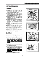
4-1. Rotary hook
[
Removal
]
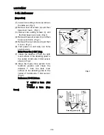
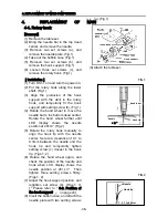
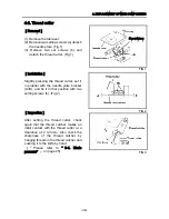
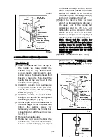
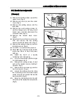
(1) Remove the table set.
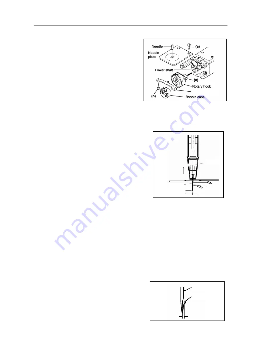
(2) Bring the needle bar to the top dead
center, and remove the needle.
(3) Remove two set screws (a), and
remove the needle plate. (Fig.1)
(4) Take out the bobbin case. (Fig.1)
(5) Remove two set screws (b), and
remove the hook support. (Fig.1)
(6) Loosen three set screws (c), and
remove the rotary hook. (Fig.1)
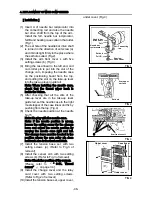
[Installation]
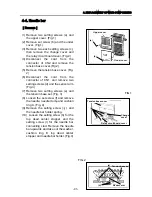
(1)
Turn DS1-1 on and turn the power on.
(2)
Put the rotary hook along the lower
shaft. (Fig.1)
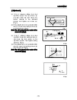
(3) Align the protrusion of the hook
support with the dent in the rotary
hook, and temporarily fit the hook
support with setting screw (b). (Fig.1)
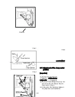
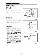
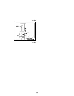
(4) Rotate the hand wheel to move the
needle bar to the bottom dead center.
Rotate the hand wheel further until
LCD display shows the needle
position at 201±3°.(Fig.2)
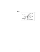
(5) Rotate the rotary hook manually to
align the hook tip with the needle
center. Secure a clearance of 0.1 to
0.3mm between the needle and the
hook tip and temporarily tighten
setting screw (c) closest to the hook
tip. (Figs.1, 2)
(6) Rotate the hand wheel again, and
check the position of the needle and
hook when LCD display shows the
needle position at 201 ± 3 ° . Then
tighten three setting screws firmly.
(Figs.1, 2)
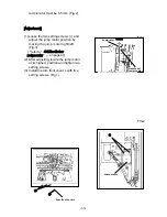
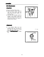
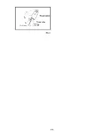
(7) Adjust the hook support position, and
retighten set screw (b). (Figs.1, 3)
[『Please refer to “ 3-2. Position of
the hook support” 』 on page 23]
(8) Insert the bobbin case, and attach the
needle plate with two setting screws
(a). (Fig.1)
4.
REPLACEMENT
OF
MAIN
(9) Attach the table set.
Hook support
FIG.1
Needle
Needle
Hook tip
bar
201
±
3
°
FIG.2
Needle
Hook tip
0.1 to 0.3mm
-36-
Содержание ESP9000
Страница 1: ...SERVICE MANUAL Embroidery Machine ESP9000 15 needles...
Страница 2: ......
Страница 13: ...FIG 3 48...
Страница 24: ...FIG 4 59...
Страница 26: ...22 Power supply and consumption 100 120 200 240VAC 50 60Hz 220W 23 Dimensions 835 H x 745 W x 740 D 2...
Страница 36: ...Connection of connector CN 10 Must be connected correctly Replace See P 47 CN10 11...
Страница 40: ...Picker height C 7 9 mm when piker solenoid is ON Adjust See P 27 15...
Страница 54: ...Connection of connector CN 7 Check the connector visually Must be connecte d correctly Replace See P 45 CN7 22...
Страница 58: ...FIG 2 FIG 3 201 3 0 1 0 3 mm 22...
Страница 63: ...FIG 4 e Drive arm FIG 5 27...
Страница 70: ...FIG 3 34...
Страница 72: ...FIG 2 FIG 3 201 3 0 1 0 3 mm 22...
Страница 74: ...FIG 2 FIG 3 Needle bar Stopper Needle bar Connecting stud 24...
Страница 77: ...FIG 4 e Drive arm FIG 5 27...
Страница 84: ...FIG 3 34...
Страница 86: ...FIG 4 31...
Страница 88: ...FIG 4 33...
Страница 90: ...FIG 2 35...
Страница 93: ...2 a Sensor arm 3 38...
Страница 95: ...FIG 3 FIG 4 VR6 Power supply board 40...
Страница 97: ...FIG 3 FIG 4 0 5 to 0 8mm 0 2mm or less Hook support hook support 37...
Страница 100: ...FIG 4 40...
Страница 103: ...FIG 2 Needle bar c Top dead center stopper needle bar connecting stud FIG 3 43...
Страница 105: ...FIG 5 45...
Страница 110: ...FIG 1 FIG 2 FIG 3 c Base cover rear R Table set a FIG 4 Rear cover b b e d Case cover upper Power circuit board f 50...
Страница 111: ...Printed in Japan 2002 8...