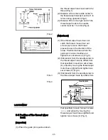

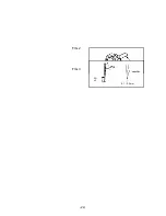

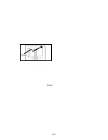
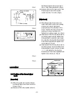


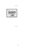
FIG.1
FIG.2
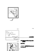
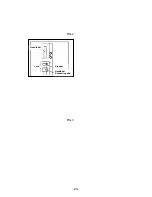
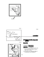
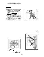
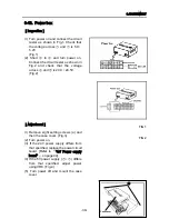
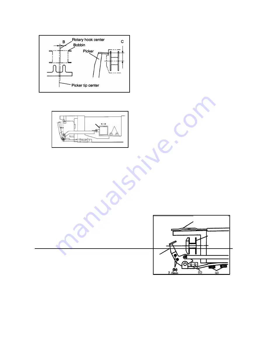
FIG.3
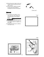
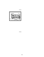
FIG.4
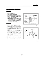
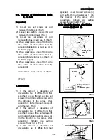
3-6 Position of the thread wiper
hook
[Inspection]
(1) When the guide pin is pushed down,
the thread wiper hook must catch the
thread. (Fig.1)
(2) Distance A from the needle center to
the thread wiper hook tip must be 11
mm or more during operation. (Fig.2)
(3) Distance B from the right end of the
thread wiper hook to the needle
center must be 1 to 3mm. (Fig.2)
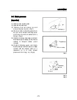
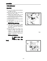
[Adjustment]
(1) If the thread wiper hook does not
catch the thread, loosen four setting
screws (a) to move the thread
presser base in the direction of the
arrow. Position the base where the
guide pin moves smoothly and
tighten four setting screws (a). (Fig.3)
ピッカーソレノイド
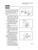
(2) If distance A from the needle center to
the thread wiper hook tip differs from
that specified, loosen two set screws
(b), adjust by moving the thread wiper
motor base right/left and tighten two
set screws (b). (Fig.3)
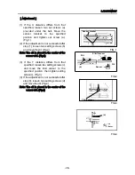
(3) If distance B from the needle center to
the thread wiper hook tip differs from
that specified, loosen two set screws
(c), and adjust by moving the
thread wiper hook base right/left and
tighten two screws (c). (Fig.3)
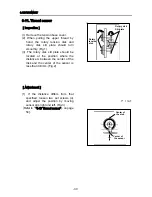
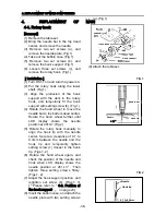
3.ADJUSTMENT
(a)
(
組
)
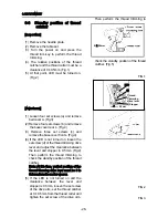
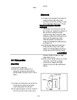
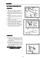
Picker solenoid
Needle plate
Bobbin
Picker
-31-
Содержание ESP9000
Страница 1: ...SERVICE MANUAL Embroidery Machine ESP9000 15 needles...
Страница 2: ......
Страница 13: ...FIG 3 48...
Страница 24: ...FIG 4 59...
Страница 26: ...22 Power supply and consumption 100 120 200 240VAC 50 60Hz 220W 23 Dimensions 835 H x 745 W x 740 D 2...
Страница 36: ...Connection of connector CN 10 Must be connected correctly Replace See P 47 CN10 11...
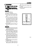
Страница 40: ...Picker height C 7 9 mm when piker solenoid is ON Adjust See P 27 15...
Страница 54: ...Connection of connector CN 7 Check the connector visually Must be connecte d correctly Replace See P 45 CN7 22...
Страница 58: ...FIG 2 FIG 3 201 3 0 1 0 3 mm 22...
Страница 63: ...FIG 4 e Drive arm FIG 5 27...
Страница 70: ...FIG 3 34...
Страница 72: ...FIG 2 FIG 3 201 3 0 1 0 3 mm 22...
Страница 74: ...FIG 2 FIG 3 Needle bar Stopper Needle bar Connecting stud 24...
Страница 77: ...FIG 4 e Drive arm FIG 5 27...
Страница 84: ...FIG 3 34...
Страница 86: ...FIG 4 31...
Страница 88: ...FIG 4 33...
Страница 90: ...FIG 2 35...
Страница 93: ...2 a Sensor arm 3 38...
Страница 95: ...FIG 3 FIG 4 VR6 Power supply board 40...
Страница 97: ...FIG 3 FIG 4 0 5 to 0 8mm 0 2mm or less Hook support hook support 37...
Страница 100: ...FIG 4 40...
Страница 103: ...FIG 2 Needle bar c Top dead center stopper needle bar connecting stud FIG 3 43...
Страница 105: ...FIG 5 45...
Страница 110: ...FIG 1 FIG 2 FIG 3 c Base cover rear R Table set a FIG 4 Rear cover b b e d Case cover upper Power circuit board f 50...
Страница 111: ...Printed in Japan 2002 8...