3.ADJUSTMENT
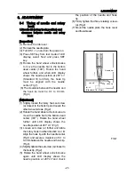
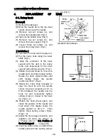
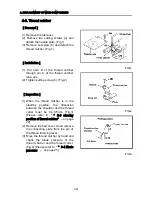
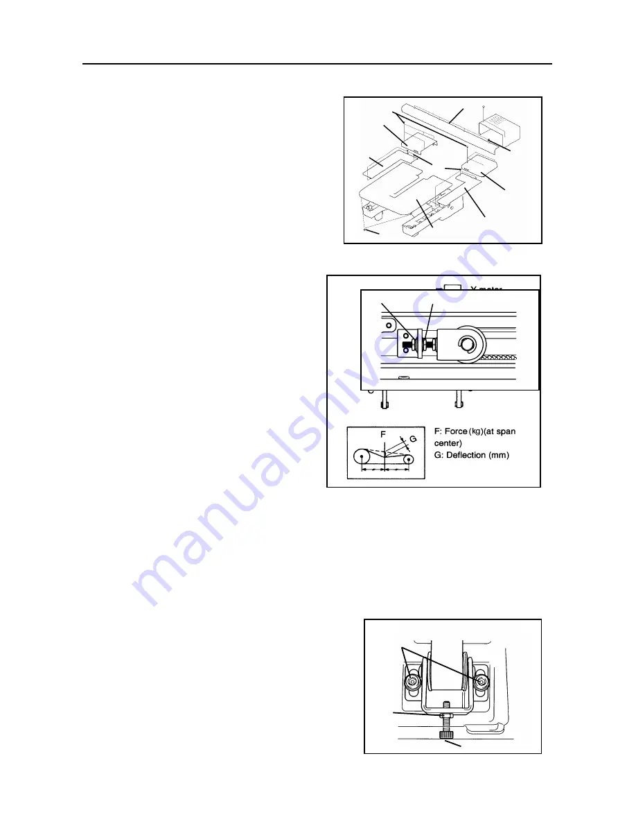
3-8. Tension of drive belts A & C
[Inspection]
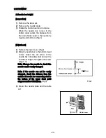
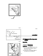
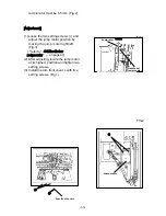
(1) Remove two setting screws (a) and
then remove the table set. (Fig.1)
(2) Remove four each set screws (b) and
then remove base cover rear R and L.
(Fig.1)
(3) Remove three each set screws (c)
and remove base cover front R and L.
(Fig.1)
(4) Remove four set screws (d) and
remove X cover. (Fig.1)
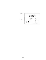
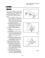
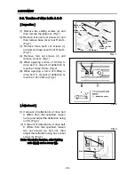
(5) When applying a force of 0.48 ㎏ to
drive belt A, amount of deflection G
must be 10.8±2.16mm. (Fig.2)
(6) When applying a force of 0.95kg to
drive belt C, amount of deflection G
must be 7.4±1.48mm. (Fig.2)
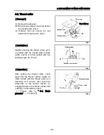
[Adjustment]
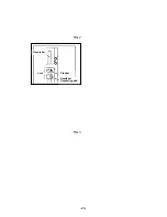
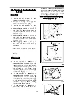
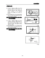
(1) If amount of deflection G of drive belt
A differs from that specified, loosen
nut (e) and adjust the deflection using
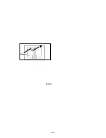
nut (f). (Fig.3)
(2) If amount of defection G of drive belt
C differs from that specified, loosen
two set screws (g) and nut, then
adjust the deflection using hex socket
screw (h). (Fig.4)
Note: Check the tension, after tighting
nuts (e),(f) and a screw (g).
FIG.1
FIG.2
FIG.3
X cover
(b)
Base cover
rear L
Base cover
front L
(d)
(c)
Base cover
rear R
(a)
Base cover
front R
Table set
(g)
(h)
Nut
(f)
(e)
-30-
Содержание ESP9000
Страница 1: ...SERVICE MANUAL Embroidery Machine ESP9000 15 needles...
Страница 2: ......
Страница 13: ...FIG 3 48...
Страница 24: ...FIG 4 59...
Страница 26: ...22 Power supply and consumption 100 120 200 240VAC 50 60Hz 220W 23 Dimensions 835 H x 745 W x 740 D 2...
Страница 36: ...Connection of connector CN 10 Must be connected correctly Replace See P 47 CN10 11...
Страница 40: ...Picker height C 7 9 mm when piker solenoid is ON Adjust See P 27 15...
Страница 54: ...Connection of connector CN 7 Check the connector visually Must be connecte d correctly Replace See P 45 CN7 22...
Страница 58: ...FIG 2 FIG 3 201 3 0 1 0 3 mm 22...
Страница 63: ...FIG 4 e Drive arm FIG 5 27...
Страница 70: ...FIG 3 34...
Страница 72: ...FIG 2 FIG 3 201 3 0 1 0 3 mm 22...
Страница 74: ...FIG 2 FIG 3 Needle bar Stopper Needle bar Connecting stud 24...
Страница 77: ...FIG 4 e Drive arm FIG 5 27...
Страница 84: ...FIG 3 34...
Страница 86: ...FIG 4 31...
Страница 88: ...FIG 4 33...
Страница 90: ...FIG 2 35...
Страница 93: ...2 a Sensor arm 3 38...
Страница 95: ...FIG 3 FIG 4 VR6 Power supply board 40...
Страница 97: ...FIG 3 FIG 4 0 5 to 0 8mm 0 2mm or less Hook support hook support 37...
Страница 100: ...FIG 4 40...
Страница 103: ...FIG 2 Needle bar c Top dead center stopper needle bar connecting stud FIG 3 43...
Страница 105: ...FIG 5 45...
Страница 110: ...FIG 1 FIG 2 FIG 3 c Base cover rear R Table set a FIG 4 Rear cover b b e d Case cover upper Power circuit board f 50...
Страница 111: ...Printed in Japan 2002 8...

