


STE 73995
– 38 –
TRANSPORTATION AND INSTALLATION MANUAL
Section 3
System Connections
3.1 Cable
Wiring
This section describes the various types of cables and connectors and explains how
these are to be connected.
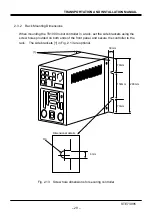
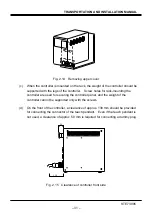
3.1.1 Connector Arrangement on the Controller
The cables connected to the TS1000 robot controller are shown in Fig. 3.1.
Front view
Fig. 3.1 TS1000 robot controller connector layout
In the subsequent paragraphs, we explain how to connect cables [1] to [5]. For
information on how to connect cables [6] to [11], refer to the Interface Manual.
COM1
HOST
TCPR
G
EXT I/O
TP
HAN
D
E
170
50
21
8
17
11
29
0
Main power supply
Rubber shoe
Operation panel
[10] OUTPUT:
For external output signal
[9] INPUT:
For external input signal
[11] EXT I/O:
For distribution I/O signal
Optional extended unit (X8L1)
[1] AC IN:
For main power supply
(AC200)
[2] MOTOR: For connecting motor
[4] HAND: For hand control cable
[3] ENC: For encoder
[8] TCPRG: For editing sequence program
[5] TP: For connecting teach pendant
[6] COM1: For serial communication
with external equipment
[7] HOST: For user serial communication
Optional distribution I/O unit (TR48DIOC)
30
Содержание TH180
Страница 10: ...STE 73995 9 TRANSPORTATION AND INSTALLATION MANUAL Fig 1 1 Robot package TH250A Fig 1 2 Robot package TH350A ...
Страница 11: ...STE 73995 10 TRANSPORTATION AND INSTALLATION MANUAL Fig 1 3 Robot package TH180 ...
Страница 21: ...STE 73995 20 TRANSPORTATION AND INSTALLATION MANUAL Fig 2 4 External view of TH350A T robot ...
Страница 43: ...STE 73995 42 TRANSPORTATION AND INSTALLATION MANUAL Fig 3 4 Robot side connector arrangement TH350A T ...
Страница 80: ...STE 73995 79 TRANSPORTATION AND INSTALLATION MANUAL APPROVED BY CHECKED BY PREPARED BY ...


