


STE 73995
– 25 –
TRANSPORTATION AND INSTALLATION MANUAL
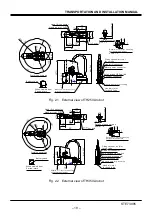
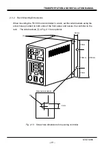
2.2.4 Installing the Robot
The robot is secured, using the set holes on the base. Use M8 hexagon socket head
cap screws.
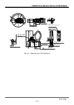
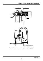
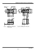
The robot installation method is shown in Figs. 2.9 to 2. 11. Reference planes are
provided on the base section and marked with “xxx”.1
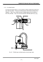
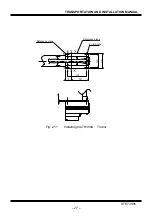
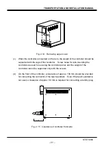
To align the robot position in the base coordinate system, or to replace the robot,
provide adequate reference planes. Then, contact such reference planes to the base
reference planes and secure the robot.
!
CAUTION
• The robot will suddenly accelerate and decelerate during operation. When
installing it on a frame, make sure that the frame has sufficient strength and
rigidity.
If the robot is installed on a frame that does not have sufficient rigidity,
vibration will occur while the robot is operating, and could lead to faults.
When installing the robot on the floor, secure the robot with anchor bolts,
etc.
• Install the robot on a level place. Failure to do so could lead to a drop in
performance or faults.
Содержание TH180
Страница 10: ...STE 73995 9 TRANSPORTATION AND INSTALLATION MANUAL Fig 1 1 Robot package TH250A Fig 1 2 Robot package TH350A ...
Страница 11: ...STE 73995 10 TRANSPORTATION AND INSTALLATION MANUAL Fig 1 3 Robot package TH180 ...
Страница 21: ...STE 73995 20 TRANSPORTATION AND INSTALLATION MANUAL Fig 2 4 External view of TH350A T robot ...
Страница 43: ...STE 73995 42 TRANSPORTATION AND INSTALLATION MANUAL Fig 3 4 Robot side connector arrangement TH350A T ...
Страница 80: ...STE 73995 79 TRANSPORTATION AND INSTALLATION MANUAL APPROVED BY CHECKED BY PREPARED BY ...


