5-13
8.
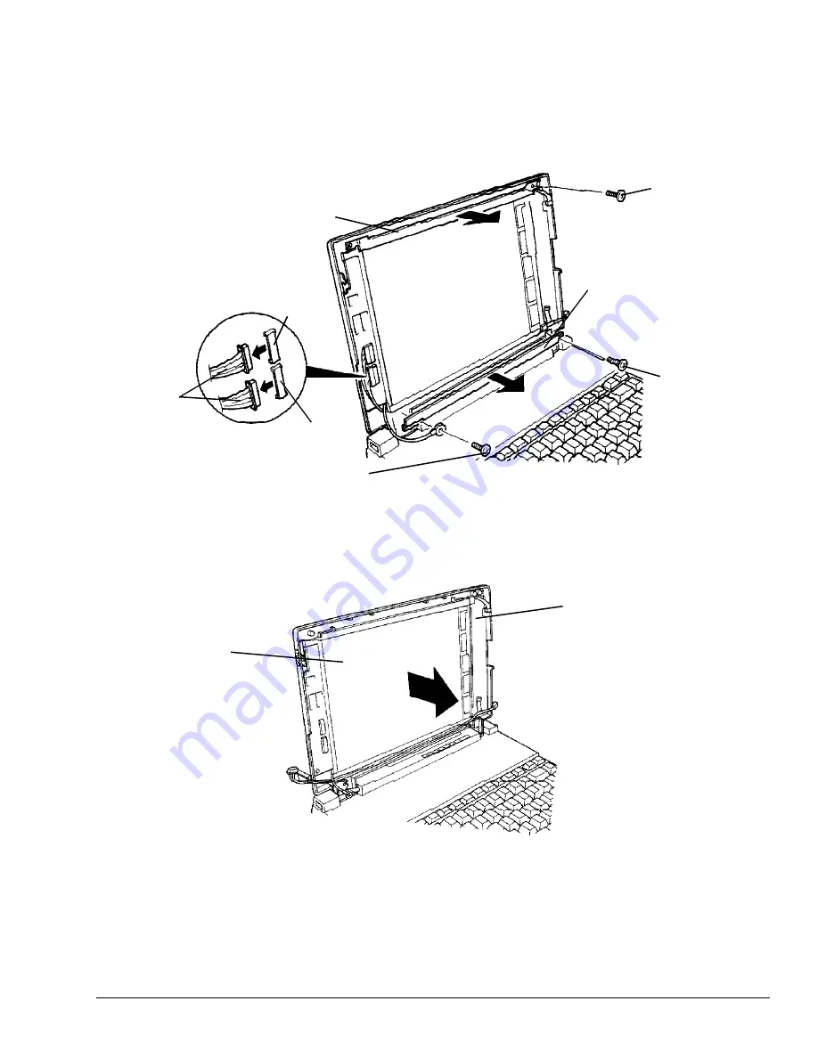
Carefully lift the mylar shielding and tape which cover the connectors on the LCD module.
Then disconnect the two display cables from CN1 and CN2 on the LCD module.
9.
Remove the one (M2x4) screw from the top display support, one (M2.5x4) screw and one
(M2.5x6 silver) screw from the bottom display support. Then remove the two display
supports (Figure 5-10).
Figure 5-10 Removing the display supports
10.
Remove the LCD module from the LCD cover and gently set it aside (Figure 5-11).
Figure 5-11 Removing the LCD module
M2.5x4
screw
display
cables
CN2
CN1
top display
support
bottom display
support
M2.5x6 silver
screw
M2x4 screw
LCD module
LCD cover
Содержание T-Series T2200sx
Страница 1: ...1 1 Chapter 1 Hardware Overview ...
Страница 2: ...1 2 This page intentionally left blank ...
Страница 4: ...1 4 This page intentionally left blank ...
Страница 16: ...1 16 This page intentionally left blank ...
Страница 17: ...2 1 Chapter 2 Operational Overview ...
Страница 18: ...2 2 This page intentionally left blank ...
Страница 42: ...2 26 2 13 Connectors Appendix B contains the pin assignments for the connectors within the T2200SX ...
Страница 43: ...3 1 Chapter 3 Troubleshooting Procedures ...
Страница 44: ...3 2 This page intentionally left blank ...
Страница 46: ...3 4 This page intentionally left blank ...
Страница 82: ...3 40 This page intentionally left blank ...
Страница 83: ...4 1 Chapter 4 Tests and Diagnostics ...
Страница 84: ...4 2 This page intentionally left blank ...
Страница 141: ...5 1 Chapter 5 Disassembly Procedures ...
Страница 142: ...5 2 This page intentionally left blank ...
Страница 144: ...5 4 This page intentionally left blank ...
Страница 169: ...6 1 Chapter 6 Reassembly Procedures ...
Страница 170: ...6 2 This page intentionally left blank ...
Страница 172: ...6 4 This page intentionally left blank ...
Страница 191: ...App 1 Appendices ...
Страница 192: ...App 2 This page intentionally left blank ...
Страница 195: ...App 5 Appendix A System Board Layout A 1 System Board FSTFGx ICs Figure A 1 System board FSTFGx ICs front A D D C B ...
Страница 196: ...App 6 Figure A 2 System board FSTFGx ICs back G G G G E F J H I K ...
Страница 198: ...App 8 This page intentionally left blank ...
Страница 199: ...App 9 A 2 System Board FSTFGx Connectors Figure A 3 System board FSTFGx connectors front M G I D B R K L L H N J O C F ...
Страница 200: ...App 10 Figure A 4 System board FSTFGx connectors back E A P Q ...
Страница 202: ...App 12 This page intentionally left blank ...
Страница 203: ...App 13 A 3 System Board FSTFGx OSCs Figure A 5 System board FSTFGx OSCs front F G H E ...
Страница 204: ...App 14 Figure A 6 System board FSTFGx OSCs back A B C D ...
Страница 215: ...App 25 Appendix C ASCII Character Codes Table C 1 ASCII character codes ...
Страница 222: ...App 32 E 3 German Keyboard Figure E 3 German keyboard E 4 French Keyboard Figure E 4 French keyboard ...


