6-9
6.5 Installing the System Board and
Power Supply Board
1.
Lay the rigid portion of the system board into position in the computer. Make sure the guide
pins are aligned and that the flexible portion of the system board is resting on the system
board support block.
2.
Route the RTC battery cable under the RTC battery and away from any screw holes as you
place the battery on the ledge provided at the back of the keyboard base.
3.
Route the PS/2 mouse cable on top of the connector and on top of the RTC battery as you
place the mouse connector into the slot on the side of the computer. Make sure the cable is
clear of all screw holes.
4.
Remove the system board support block and fold the flexible portion of the system board
into position in the computer.
5.
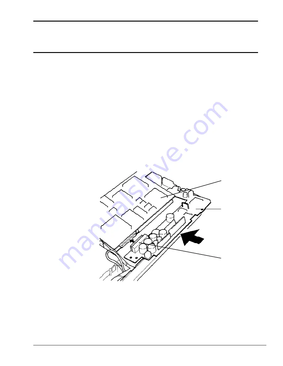
Slightly lift the system board and firmly connect it to the power supply board at PJ9 on the
power supply board (Figure 6-4).
Figure 6-4 Positioning the power supply board
6.
Insert the joined boards into the computer. Make sure the boards are aligned with the guide
pins and that the metal tab on the system board is over the power supply board.
7.
Install the one (M2x4) screw that secures the system board and power supply board to the
computer (Figure 6-5).
8.
Place the flexible portion of the system board onto the system board support block.
PJ9
power supply
board
system board
Содержание T-Series T2200sx
Страница 1: ...1 1 Chapter 1 Hardware Overview ...
Страница 2: ...1 2 This page intentionally left blank ...
Страница 4: ...1 4 This page intentionally left blank ...
Страница 16: ...1 16 This page intentionally left blank ...
Страница 17: ...2 1 Chapter 2 Operational Overview ...
Страница 18: ...2 2 This page intentionally left blank ...
Страница 42: ...2 26 2 13 Connectors Appendix B contains the pin assignments for the connectors within the T2200SX ...
Страница 43: ...3 1 Chapter 3 Troubleshooting Procedures ...
Страница 44: ...3 2 This page intentionally left blank ...
Страница 46: ...3 4 This page intentionally left blank ...
Страница 82: ...3 40 This page intentionally left blank ...
Страница 83: ...4 1 Chapter 4 Tests and Diagnostics ...
Страница 84: ...4 2 This page intentionally left blank ...
Страница 141: ...5 1 Chapter 5 Disassembly Procedures ...
Страница 142: ...5 2 This page intentionally left blank ...
Страница 144: ...5 4 This page intentionally left blank ...
Страница 169: ...6 1 Chapter 6 Reassembly Procedures ...
Страница 170: ...6 2 This page intentionally left blank ...
Страница 172: ...6 4 This page intentionally left blank ...
Страница 191: ...App 1 Appendices ...
Страница 192: ...App 2 This page intentionally left blank ...
Страница 195: ...App 5 Appendix A System Board Layout A 1 System Board FSTFGx ICs Figure A 1 System board FSTFGx ICs front A D D C B ...
Страница 196: ...App 6 Figure A 2 System board FSTFGx ICs back G G G G E F J H I K ...
Страница 198: ...App 8 This page intentionally left blank ...
Страница 199: ...App 9 A 2 System Board FSTFGx Connectors Figure A 3 System board FSTFGx connectors front M G I D B R K L L H N J O C F ...
Страница 200: ...App 10 Figure A 4 System board FSTFGx connectors back E A P Q ...
Страница 202: ...App 12 This page intentionally left blank ...
Страница 203: ...App 13 A 3 System Board FSTFGx OSCs Figure A 5 System board FSTFGx OSCs front F G H E ...
Страница 204: ...App 14 Figure A 6 System board FSTFGx OSCs back A B C D ...
Страница 215: ...App 25 Appendix C ASCII Character Codes Table C 1 ASCII character codes ...
Страница 222: ...App 32 E 3 German Keyboard Figure E 3 German keyboard E 4 French Keyboard Figure E 4 French keyboard ...


