


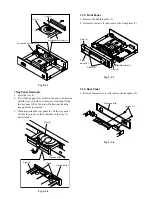
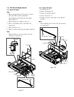


1-3-4. Pickup Mechanism Assembly
<Removal>
1. Turn over the mechanism chassis assembly (1).
2. Remove the flexible cables (2) at two locations.
3. Remove four screws (3) and remove the pickup
mechanism assembly (4).
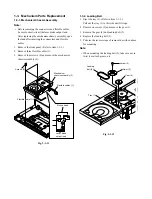
<Mounting>
1. Replace the pickup mechanism assembly (4) with a
new one.
Remove dampers from the old pickup mechanism
assembly used and mount the dampers on the new
pickup mechanism assembly.
2. When mounting, perform the reverse steps of the
removal described above.
Fig. 2-1-16
Note:
• The dampers’ color differs when used for the front
side and the rear.
• When mounting the pickup mechanism assembly (4)
with the screws (3), push the pickup mechanism
assembly (4) downward without being caught and
tighten the screws (3) after placing the washer with the
damper bent.
Fig. 2-1-17
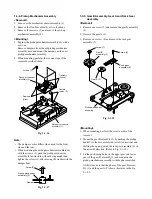
1-3-5. Gear B Assembly, Gear A and Rack Gear
Assembly
<Removal>
1. Remove one screw (1) and remove the gear B assembly
(2).
2. Remove the gear A (3).
3. Remove one screw (4) and remove the rack gear
assembly (5).
Fig. 2-1-18
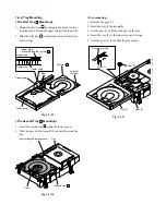
<Mounting>
1. When mounting, perform the reverse order of the
removal.
2. Mount the gear B assembly (1) by pushing the pickup
head (5) to the disc motor side (arrow A direction) and
shifting the upper gear of the rack gear assembly (4) in
the arrow B direction. (Refer to Fig. 2-1-19.)
3. Fit the positioning holes on the upper gear and lower
gear of the gear B assembly (1) and mount on the
pickup mechanism assembly with the phase matched.
At this time, note that the phase of the gear B assem-
bly (1) and the gear A (2) shows the status in the Fig.
2-1-20.
Mechanism chassis
assembly (1)
Flexible
cables (2)
Screws (3)
Dampers
(Green)
Dampers
(Gray)
Pickup mechanism
assembly (4)
Damper
Screw (3)
Pickup mechanism
assembly (4)
Screw (4)
Screw (1)
Rack gear
assembly (5)
Gear A (3)
Gear B
assembly (2)
Pickup mechanism
assembly
Содержание SD-2050
Страница 1: ...DVD VIDEO PLAYER SERVICE MANUAL May 2000 s FILE NO 810 200005 SD 2050 DIGITAL VIDEO ...
Страница 5: ...SECTION 1 GENERAL DESCRIPTIONS SECTION 1 GENERAL DESCRIPTIONS 1 OPERATING INSTRUCTIONS ...
Страница 51: ...47 Others Memo ...
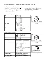
Страница 80: ...4 2 Power Supply Block Diagram Fig 3 4 2 ...
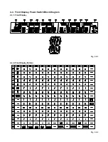
Страница 82: ...Fig 3 4 5 4 3 3 Front Display Power Switch Block Diagram ...
Страница 84: ...Fig 3 4 7 4 4 2 Logical System Block Diagram ...
Страница 85: ...4 5 Output Block Diagram Fig 3 4 8 ...
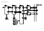
Страница 86: ...10 1 3 4 A B C D E G 2 5 6 7 8 9 F Fig 3 5 1 5 CIRCUIT DIAGRAMS 5 1 Power Supply Circuit Diagram ...
Страница 88: ...10 1 3 4 A B C D E G 2 5 6 7 8 9 F Fig 3 5 3 5 2 Front Display Power Switch Circuit Diagram ...
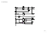
Страница 95: ...Fig 3 5 5 5 3 2 Main Circuit Diagram ...
Страница 96: ...5 3 2 Main Circuit Diagram ...
Страница 97: ......
Страница 98: ......
Страница 99: ......
Страница 100: ......
Страница 101: ......
Страница 102: ......
Страница 103: ...Fig 3 5 5 ...
Страница 105: ...Fig 3 5 6 10 1 3 4 A B C D E G 2 5 6 7 8 9 F 11 H 5 4 Output Circuit Diagram ...
Страница 115: ...10 1 3 4 A B C D E G 2 5 6 7 8 9 F Fig 3 6 6 EU01 Main PC Board Top pattern character symbol ...
Страница 116: ...10 1 3 4 A B C D E G 2 5 6 7 8 9 F Fig 3 6 7 EU01 Main PC Board Bottom pattern character symbol ...
Страница 120: ...4 EXPLODED VIEWS 4 1 Packing Assembly Fig 4 4 1 ZF01 ZF27 ZF17 ZF10 ZF11 ZF23 ZF30 ZK04 ZK01 ZK03 ZK02 ...
Страница 125: ......


