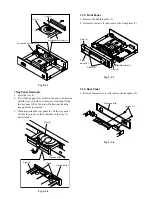
1-1-3. Front Panel
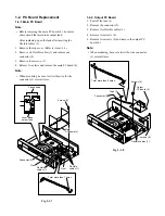
1. Remove the flexible cable (1).
2. Release four claws (2) and remove the front panel (3).
Fig. 2-1-5
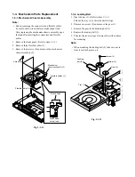
1-1-4. Rear Panel
1. Remove three screws (1) and remove the rear panel (2).
Fig. 2-1-6
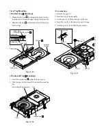
Fig. 2-1-3
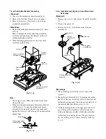
<Tray Panel Removal>
1. Eject the tray (3).
2. Twist the tray panel (4) a little in the arrow A direction
with the tray (3) held to release two claws and lift up
the tray panel (4) in the arrow B direction, then the
tray panel (4) is removed.
3. When mounting the tray panel (4), fit the tray panel
(4) into the groove of the both sides of the tray (3)
until it clicks.
Fig. 2-1-4
Tray (5)
Gear (4)
Mechanism assembly (3)
Mechanism assembly (3)
A
B
Tray panel (4)
Tray (3)
Tray panel (4)
Claws
Tray (3)
Claws (2)
Front
panel (3)
Claw (2)
Flexible cable (1)
Claw (2)
Rear panel (2)
Screws (1)
Содержание SD-2050
Страница 1: ...DVD VIDEO PLAYER SERVICE MANUAL May 2000 s FILE NO 810 200005 SD 2050 DIGITAL VIDEO ...
Страница 5: ...SECTION 1 GENERAL DESCRIPTIONS SECTION 1 GENERAL DESCRIPTIONS 1 OPERATING INSTRUCTIONS ...
Страница 51: ...47 Others Memo ...
Страница 80: ...4 2 Power Supply Block Diagram Fig 3 4 2 ...
Страница 82: ...Fig 3 4 5 4 3 3 Front Display Power Switch Block Diagram ...
Страница 84: ...Fig 3 4 7 4 4 2 Logical System Block Diagram ...
Страница 85: ...4 5 Output Block Diagram Fig 3 4 8 ...
Страница 86: ...10 1 3 4 A B C D E G 2 5 6 7 8 9 F Fig 3 5 1 5 CIRCUIT DIAGRAMS 5 1 Power Supply Circuit Diagram ...
Страница 88: ...10 1 3 4 A B C D E G 2 5 6 7 8 9 F Fig 3 5 3 5 2 Front Display Power Switch Circuit Diagram ...
Страница 95: ...Fig 3 5 5 5 3 2 Main Circuit Diagram ...
Страница 96: ...5 3 2 Main Circuit Diagram ...
Страница 97: ......
Страница 98: ......
Страница 99: ......
Страница 100: ......
Страница 101: ......
Страница 102: ......
Страница 103: ...Fig 3 5 5 ...
Страница 105: ...Fig 3 5 6 10 1 3 4 A B C D E G 2 5 6 7 8 9 F 11 H 5 4 Output Circuit Diagram ...
Страница 115: ...10 1 3 4 A B C D E G 2 5 6 7 8 9 F Fig 3 6 6 EU01 Main PC Board Top pattern character symbol ...
Страница 116: ...10 1 3 4 A B C D E G 2 5 6 7 8 9 F Fig 3 6 7 EU01 Main PC Board Bottom pattern character symbol ...
Страница 120: ...4 EXPLODED VIEWS 4 1 Packing Assembly Fig 4 4 1 ZF01 ZF27 ZF17 ZF10 ZF11 ZF23 ZF30 ZK04 ZK01 ZK03 ZK02 ...
Страница 125: ......

