35
Function setup
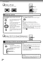
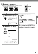
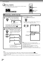
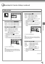
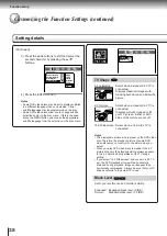
Setting procedure
Customizing the Function Settings
You can change the default settings to customize performance to your preference.
Press SETUP during stop.
The following on-screen display
appears.
Press / to select a symbol for the
setting you want to change.
(See the next page.)
Language settings
Picture performance settings
Output sound settings
Display settings
Operational settings
2
3
1
Notes
• The on-screen display disappears when you press the
SETUP button.
• The SETUP button can function even during normal
playback, however some operations may be inaccessible,
and a message will appear. In this case, try again after
playback is stopped.
Press / to select the setting you
want to change, then press ENTER.
Change the selection by / or other
buttons, referring to the pages from 37,
then press ENTER.
Repeat steps 3 and 4 to change other
settings.
To select another symbol, go back to step 2.
Press SETUP.
The on-screen display disappears.
4
5
6
To return to the previous display
Press RETURN.
Function setup
PICTURE
DISPLAY
OPERATION
LANGUAGE
AUDIO
DVD
VCD
CD
LANGUAGE
PICTURE
AUDIO
DISPLAY
OPERATION
ENTER
ENTER
PICTURE
DISPLAY
OPERATION
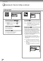
Audio Language
Subtitle Language
LANGUAGE
Disc Menu Language
ENG
– – –
ENG
AUDIO
On-Screen Language
ENG
SETUP
ENTER
SETUP
RETURN
RETURN
3, 4
2
1, 6
ENTER
ENTER
Содержание SD-2050
Страница 1: ...DVD VIDEO PLAYER SERVICE MANUAL May 2000 s FILE NO 810 200005 SD 2050 DIGITAL VIDEO ...
Страница 5: ...SECTION 1 GENERAL DESCRIPTIONS SECTION 1 GENERAL DESCRIPTIONS 1 OPERATING INSTRUCTIONS ...
Страница 51: ...47 Others Memo ...
Страница 80: ...4 2 Power Supply Block Diagram Fig 3 4 2 ...
Страница 82: ...Fig 3 4 5 4 3 3 Front Display Power Switch Block Diagram ...
Страница 84: ...Fig 3 4 7 4 4 2 Logical System Block Diagram ...
Страница 85: ...4 5 Output Block Diagram Fig 3 4 8 ...
Страница 86: ...10 1 3 4 A B C D E G 2 5 6 7 8 9 F Fig 3 5 1 5 CIRCUIT DIAGRAMS 5 1 Power Supply Circuit Diagram ...
Страница 88: ...10 1 3 4 A B C D E G 2 5 6 7 8 9 F Fig 3 5 3 5 2 Front Display Power Switch Circuit Diagram ...
Страница 95: ...Fig 3 5 5 5 3 2 Main Circuit Diagram ...
Страница 96: ...5 3 2 Main Circuit Diagram ...
Страница 97: ......
Страница 98: ......
Страница 99: ......
Страница 100: ......
Страница 101: ......
Страница 102: ......
Страница 103: ...Fig 3 5 5 ...
Страница 105: ...Fig 3 5 6 10 1 3 4 A B C D E G 2 5 6 7 8 9 F 11 H 5 4 Output Circuit Diagram ...
Страница 115: ...10 1 3 4 A B C D E G 2 5 6 7 8 9 F Fig 3 6 6 EU01 Main PC Board Top pattern character symbol ...
Страница 116: ...10 1 3 4 A B C D E G 2 5 6 7 8 9 F Fig 3 6 7 EU01 Main PC Board Bottom pattern character symbol ...
Страница 120: ...4 EXPLODED VIEWS 4 1 Packing Assembly Fig 4 4 1 ZF01 ZF27 ZF17 ZF10 ZF11 ZF23 ZF30 ZK04 ZK01 ZK03 ZK02 ...
Страница 125: ......


