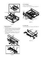
1-3-3. Loading Motor
<Removal>
1. Remove the loading belt. (Refer to item 1-3-2.)
2. Remove two screws (1).
3. Remove four screws (2) and remove the loading motor
(3) (with the loading motor PC board (4) attached).
4. Desolder the terminal part of the loading motor (3)
and remove the loading motor PC board (4).
5. Replace the loading motor (3).
Fig. 2-1-13
<Mounting>
1. Eject the second tray
2
. (Set the POM mark of the
cam to the position as shown in Fig. 2-1-14.)
Screws (1)
Screws (2)
Loading motor (3)
SW1
SW3
SW2
Loading motor
PC board (4)
Fig. 2-1-14
2. Solder the terminals of the loading motor (3) on the
loading motor PC board (4) .
3. Since the switch of SW3 comes over the external
peripheral portion of the cam, push the switch by
inserting a spacer to the clearance between the chassis
and the loading motor PC board (4). (Refer to Fig. A.)
4. With the loading motor PC board (4) held, tighten two
screws (2)-1 on the loading motor (3) side and then fix
two screws (2)-2.
5. Tighten two screws (1).
6. Mount the loading belt.
7. Close the second tray
2
.
Fig. 2-1-15
POM
Cam
Chassis
POM mark
position
Second tray 2
Eject
Screws (2)-2
Screws (1)
Screws (2)-1
Loading motor
PC board (4)
Loading motor
PC board (4)
Loading
motor (3)
SW3
SW3
SW3
Cam
Push
Cam
Cam
Chassis
Chassis
Second tray 2
Spacer
Fig. A
Содержание SD-2050
Страница 1: ...DVD VIDEO PLAYER SERVICE MANUAL May 2000 s FILE NO 810 200005 SD 2050 DIGITAL VIDEO ...
Страница 5: ...SECTION 1 GENERAL DESCRIPTIONS SECTION 1 GENERAL DESCRIPTIONS 1 OPERATING INSTRUCTIONS ...
Страница 51: ...47 Others Memo ...
Страница 80: ...4 2 Power Supply Block Diagram Fig 3 4 2 ...
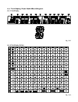
Страница 82: ...Fig 3 4 5 4 3 3 Front Display Power Switch Block Diagram ...
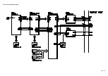
Страница 84: ...Fig 3 4 7 4 4 2 Logical System Block Diagram ...
Страница 85: ...4 5 Output Block Diagram Fig 3 4 8 ...
Страница 86: ...10 1 3 4 A B C D E G 2 5 6 7 8 9 F Fig 3 5 1 5 CIRCUIT DIAGRAMS 5 1 Power Supply Circuit Diagram ...
Страница 88: ...10 1 3 4 A B C D E G 2 5 6 7 8 9 F Fig 3 5 3 5 2 Front Display Power Switch Circuit Diagram ...
Страница 95: ...Fig 3 5 5 5 3 2 Main Circuit Diagram ...
Страница 96: ...5 3 2 Main Circuit Diagram ...
Страница 97: ......
Страница 98: ......
Страница 99: ......
Страница 100: ......
Страница 101: ......
Страница 102: ......
Страница 103: ...Fig 3 5 5 ...
Страница 105: ...Fig 3 5 6 10 1 3 4 A B C D E G 2 5 6 7 8 9 F 11 H 5 4 Output Circuit Diagram ...
Страница 115: ...10 1 3 4 A B C D E G 2 5 6 7 8 9 F Fig 3 6 6 EU01 Main PC Board Top pattern character symbol ...
Страница 116: ...10 1 3 4 A B C D E G 2 5 6 7 8 9 F Fig 3 6 7 EU01 Main PC Board Bottom pattern character symbol ...
Страница 120: ...4 EXPLODED VIEWS 4 1 Packing Assembly Fig 4 4 1 ZF01 ZF27 ZF17 ZF10 ZF11 ZF23 ZF30 ZK04 ZK01 ZK03 ZK02 ...
Страница 125: ......


