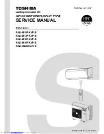
SERVICE MANUAL
FILE No. A11-017
AIR CONDITIONER (SPLIT TYPE)
Model name:
RAS-M10PKVP-ERAS-M13PKVP-ERAS-M16PKVP-ERAS-M18PKVP-ERAS-3M26UAV-E
PRINTED IN JAPAN, Jan. 2012, TDOC
Страница 1: ...SERVICE MANUAL FILE No A11 017 AIR CONDITIONER SPLIT TYPE Model name RAS M10PKVP E RAS M13PKVP E RAS M16PKVP E RAS M18PKVP E RAS 3M26UAV E PRINTED IN JAPAN Jan 2012 TDOC ...
Страница 2: ...n Views 34 5 Wiring Diagram 36 6 Specifications of Electrical Parts 38 7 Refrigerant Cycle Diagram 39 8 Control Block Diagram 44 9 Operation Description 46 10 Installation Procedure 72 11 How to Diagnose the Trouble 91 12 How to Replace the Main Parts 118 13 Exploded Views and Parts List 138 ...
Страница 3: ...410A air conditioner circuit To prevent mixing of refrigerant or refrigerating machine oil the sizes of connecting sections of charging port on main unit and installation tools are different from those used for the conventional refrigerant units Accordingly special tools are required for the new refrigerant R410A units For connecting pipes use new and clean piping materials with high pressure fitt...
Страница 4: ...ERATION CIRCUIT IF AIR OR ANY OTHER GAS IS MIXED IN THE REFRIGERANT THE GAS PRESSURE IN THE REFRIGERATION CIRCUIT WILL BECOME ABNORMALLY HIGH AND IT MAY RESULT IN THE PIPE BURSTING AND POSSIBLE PERSONNEL INJURIES IN THE EVENT THAT THE REFRIGERANT GAS LEAKS OUT OF THE PIPE DURING THE SERVICE WORK AND THE INSTALLATION WORK IMMEDIATELY LET FRESH AIR INTO THE ROOM IF THE REFRIGERANT GAS IS HEATED SUCH...
Страница 5: ...u cannot connect only one indoor unit Be sure to connect indoor units in two or more The contents noted in this service manual limit the indoor units to the RAS M10PKVP E RAS M13PKVP E RAS M16PKVP E RAS M18PKVP E For other indoor units that can also be used in combination see the Service Manual of each indoor unit Type Outdoor unit Indoor unit Heat pump RAS 3M26UAV E RAS M10PKVP E RAS M13PKVP E RA...
Страница 6: ... 295 295 295 Width mm 790 790 790 790 Depth mm 242 242 242 242 Net weight kg 12 12 12 12 Fan motor output W 30 30 30 30 Air flow rate Cooling Heating m h 640 640 690 690 750 750 800 800 Outdoor unit Unit model RAS 3M26UAV E Dimension High mm 890 Width mm 900 Depth mm 320 Net weight kg 69 Compressor Motor output W 2000 Type Twin rotary type with DC inverter variable speed control Model DA220A2F 22L...
Страница 7: ... 2 5 6 3 640 1900 3 64 8 81 80 98 13 10 3 41 2 49 5 9 1700 8 13 95 3 47 48 63 2 7 6 6 660 2220 3 75 10 30 80 98 16 10 3 94 2 36 6 3 2000 9 57 95 3 15 48 63 2 9 6 9 670 2400 3 81 11 13 80 98 18 10 4 09 2 21 6 3 2000 9 57 95 3 15 48 63 2 9 7 1 670 2400 3 81 11 13 80 98 22 10 4 69 2 11 6 8 2200 10 53 95 3 09 48 63 3 0 7 4 690 2450 3 92 11 36 80 98 24 10 5 22 1 98 7 2 2300 11 00 95 3 13 48 63 3 2 7 8 ...
Страница 8: ...9 0 980 2800 4 95 12 99 90 98 10 10 10 2 50 2 50 2 50 7 5 2000 9 57 95 3 75 48 63 3 9 8 6 960 2750 4 85 12 76 90 98 13 10 10 3 05 2 23 2 23 7 5 2000 9 57 95 3 75 48 63 4 0 8 8 970 2770 4 90 12 85 90 98 16 10 10 3 41 2 05 2 05 7 5 2000 9 57 95 3 75 48 63 4 0 8 8 970 2770 4 90 12 85 90 98 18 10 10 3 61 1 95 1 95 7 5 2000 9 57 95 3 75 48 63 4 0 8 8 970 2770 4 90 12 85 90 98 22 10 10 3 95 1 78 1 78 7 ...
Страница 9: ...9 0 980 2800 4 95 12 99 90 98 24 16 13 3 48 2 21 1 81 7 5 2000 9 57 95 3 75 48 63 4 1 9 0 980 2800 4 95 12 99 90 98 16 16 16 2 50 2 50 2 50 7 5 2000 9 57 95 3 75 48 63 4 1 9 0 980 2800 4 95 12 99 90 98 18 16 16 2 68 2 41 2 41 7 5 2000 9 57 95 3 75 48 63 4 1 9 0 980 2800 4 95 12 99 90 98 22 16 16 3 00 2 25 2 25 7 5 2000 9 57 95 3 75 48 63 4 1 9 0 980 2800 4 95 12 99 90 98 Power supply V Operating S...
Страница 10: ...1 5 9 5 320 3200 1 94 14 84 75 98 18 10 4 74 3 16 7 9 2450 11 72 95 3 22 49 64 1 5 9 8 320 3200 1 94 14 84 75 98 22 10 5 28 3 02 8 3 2500 11 96 95 3 32 49 64 1 5 10 1 320 3250 1 94 15 07 75 98 24 10 5 76 2 84 8 6 2550 12 20 95 3 37 49 64 1 5 10 4 320 3250 1 94 15 07 75 98 13 13 3 95 3 95 7 9 2450 11 72 95 3 22 49 64 1 5 9 8 320 3200 1 94 14 84 75 98 16 13 4 35 3 95 8 3 2500 11 96 95 3 32 49 64 1 5...
Страница 11: ...11 0 380 2830 2 16 13 13 80 98 16 10 10 3 67 2 67 2 67 9 0 2200 10 53 95 4 09 49 64 2 0 11 0 380 2830 2 16 13 13 80 98 18 10 10 3 86 2 57 2 57 9 0 2200 10 53 95 4 09 49 64 2 0 11 0 380 2830 2 16 13 13 80 98 22 10 10 4 20 2 40 2 40 9 0 2200 10 53 95 4 09 49 64 2 0 11 0 380 2830 2 16 13 13 80 98 24 10 10 4 53 2 24 2 24 9 0 2200 10 53 95 4 09 49 64 2 0 11 0 380 2830 2 16 13 13 80 98 13 13 10 3 21 3 2...
Страница 12: ...11 2 380 2900 2 16 13 45 80 98 16 16 16 3 00 3 00 3 00 9 0 2200 10 53 95 4 09 49 64 2 0 11 2 380 2900 2 16 13 45 80 98 18 16 16 3 18 2 91 2 91 9 0 2200 10 53 95 4 09 49 64 2 0 11 2 380 2900 2 16 13 45 80 98 22 16 16 3 50 2 75 2 75 9 0 2200 10 53 95 4 09 49 64 2 0 11 2 380 2900 2 16 13 45 80 98 Power supply V Operating Statu Indoor unit Unit Capacity Total Outdoor noise dB A B C A B C Heating capac...
Страница 13: ...5 3 15 48 63 2 9 6 9 670 2400 3 64 10 65 80 98 18 10 4 09 2 21 6 3 2000 9 15 95 3 15 48 63 2 9 7 1 670 2400 3 64 10 65 80 98 22 10 4 69 2 11 6 8 2200 10 07 95 3 09 48 63 3 0 7 4 690 2450 3 75 10 87 80 98 24 10 5 22 1 98 7 2 2300 10 53 95 3 13 48 63 3 2 7 8 700 2500 3 80 11 09 80 98 13 13 3 15 3 15 6 3 2000 9 15 95 3 15 48 63 2 9 7 1 670 2400 3 64 10 65 80 98 16 13 3 73 3 07 6 8 2200 10 07 95 3 09 ...
Страница 14: ...8 8 970 2770 4 69 12 29 90 98 16 10 10 3 41 2 05 2 05 7 5 2000 9 15 95 3 75 48 63 4 0 8 8 970 2770 4 69 12 29 90 98 18 10 10 3 61 1 95 1 95 7 5 2000 9 15 95 3 75 48 63 4 0 8 8 970 2770 4 69 12 29 90 98 22 10 10 3 95 1 78 1 78 7 5 2000 9 15 95 3 75 48 63 4 0 8 8 970 2770 4 69 12 29 90 98 24 10 10 4 26 1 62 1 62 7 5 2000 9 15 95 3 75 48 63 4 0 8 8 970 2770 4 69 12 29 90 98 13 13 10 2 75 2 75 2 00 7 ...
Страница 15: ...9 0 980 2800 4 73 12 42 90 98 16 16 16 2 50 2 50 2 50 7 5 2000 9 15 95 3 75 48 63 4 1 9 0 980 2800 4 73 12 42 90 98 18 16 16 2 68 2 41 2 41 7 5 2000 9 15 95 3 75 48 63 4 1 9 0 980 2800 4 73 12 42 90 98 22 16 16 3 00 2 25 2 25 7 5 2000 9 15 95 3 75 48 63 4 1 9 0 980 2800 4 73 12 42 90 98 Power supply V Operating Statu Indoor unit Unit Capacity Total Outdoor noise dB A B C A B C Cooling capacity kW ...
Страница 16: ...95 3 22 49 64 1 5 9 5 320 3200 1 86 14 20 75 98 18 10 4 74 3 16 7 9 2450 11 21 95 3 22 49 64 1 5 9 8 320 3200 1 86 14 20 75 98 22 10 5 28 3 02 8 3 2500 11 44 95 3 32 49 64 1 5 10 1 320 3250 1 86 14 42 75 98 24 10 5 76 2 84 8 6 2550 11 67 95 3 37 49 64 1 5 10 4 320 3250 1 86 14 42 75 98 13 13 3 95 3 95 7 9 2450 11 21 95 3 22 49 64 1 5 9 8 320 3200 1 86 14 20 75 98 16 13 4 35 3 95 8 3 2500 11 44 95 ...
Страница 17: ...1 0 380 2830 2 07 12 56 80 98 16 10 10 3 67 2 67 2 67 9 0 2200 10 07 95 4 09 49 64 2 0 11 0 380 2830 2 07 12 56 80 98 18 10 10 3 86 2 57 2 57 9 0 2200 10 07 95 4 09 49 64 2 0 11 0 380 2830 2 07 12 56 80 98 22 10 10 4 20 2 40 2 40 9 0 2200 10 07 95 4 09 49 64 2 0 11 0 380 2830 2 07 12 56 80 98 24 10 10 4 53 2 24 2 24 9 0 2200 10 07 95 4 09 49 64 2 0 11 0 380 2830 2 07 12 56 80 98 13 13 10 3 21 3 21...
Страница 18: ...11 2 380 2900 2 07 12 87 80 98 16 16 16 3 00 3 00 3 00 9 0 2200 10 07 95 4 09 49 64 2 0 11 2 380 2900 2 07 12 87 80 98 18 16 16 3 18 2 91 2 91 9 0 2200 10 07 95 4 09 49 64 2 0 11 2 380 2900 2 07 12 87 80 98 22 16 16 3 50 2 75 2 75 9 0 2200 10 07 95 4 09 49 64 2 0 11 2 380 2900 2 07 12 87 80 98 Power supply V Operating Statu Indoor unit Unit Capacity Total Outdoor noise dB A B C A B C Heating capac...
Страница 19: ...95 3 15 48 63 2 9 6 9 670 2400 3 49 10 20 80 98 18 10 4 09 2 21 6 3 2000 8 77 95 3 15 48 63 2 9 7 1 670 2400 3 49 10 20 80 98 22 10 4 69 2 11 6 8 2200 9 65 95 3 09 48 63 3 0 7 4 690 2450 3 59 10 42 80 98 24 10 5 22 1 98 7 2 2300 10 09 95 3 13 48 63 3 2 7 8 700 2500 3 65 10 63 80 98 13 13 3 15 3 15 6 3 2000 8 77 95 3 15 48 63 2 9 7 1 670 2400 3 49 10 20 80 98 16 13 3 73 3 07 6 8 2200 9 65 95 3 09 4...
Страница 20: ...8 8 970 2770 4 49 11 78 90 98 16 10 10 3 41 2 05 2 05 7 5 2000 8 77 95 3 75 48 63 4 0 8 8 970 2770 4 49 11 78 90 98 18 10 10 3 61 1 95 1 95 7 5 2000 8 77 95 3 75 48 63 4 0 8 8 970 2770 4 49 11 78 90 98 22 10 10 3 95 1 78 1 78 7 5 2000 8 77 95 3 75 48 63 4 0 8 8 970 2770 4 49 11 78 90 98 24 10 10 4 26 1 62 1 62 7 5 2000 8 77 95 3 75 48 63 4 0 8 8 970 2770 4 49 11 78 90 98 13 13 10 2 75 2 75 2 00 7 ...
Страница 21: ...9 0 980 2800 4 54 11 90 90 98 16 16 16 2 50 2 50 2 50 7 5 2000 8 77 95 3 75 48 63 4 1 9 0 980 2800 4 54 11 90 90 98 18 16 16 2 68 2 41 2 41 7 5 2000 8 77 95 3 75 48 63 4 1 9 0 980 2800 4 54 11 90 90 98 22 16 16 3 00 2 25 2 25 7 5 2000 8 77 95 3 75 48 63 4 1 9 0 980 2800 4 54 11 90 90 98 Power supply V Operating Statu Indoor unit Unit Capacity Total Outdoor noise dB A B C A B C Cooling capacity kW ...
Страница 22: ... 95 3 22 49 64 1 5 9 5 320 3200 1 78 13 61 75 98 18 10 4 74 3 16 7 9 2450 10 75 95 3 22 49 64 1 5 9 8 320 3200 1 78 13 61 75 98 22 10 5 28 3 02 8 3 2500 10 96 95 3 32 49 64 1 5 10 1 320 3250 1 78 13 82 75 98 24 10 5 76 2 84 8 6 2550 11 18 95 3 37 49 64 1 5 10 4 320 3250 1 78 13 82 75 98 13 13 3 95 3 95 7 9 2450 10 75 95 3 22 49 64 1 5 9 8 320 3200 1 78 13 61 75 98 16 13 4 35 3 95 8 3 2500 10 96 95...
Страница 23: ...11 0 380 2830 1 98 12 03 80 98 16 10 10 3 67 2 67 2 67 9 0 2200 9 65 95 4 09 49 64 2 0 11 0 380 2830 1 98 12 03 80 98 18 10 10 3 86 2 57 2 57 9 0 2200 9 65 95 4 09 49 64 2 0 11 0 380 2830 1 98 12 03 80 98 22 10 10 4 20 2 40 2 40 9 0 2200 9 65 95 4 09 49 64 2 0 11 0 380 2830 1 98 12 03 80 98 24 10 10 4 53 2 24 2 24 9 0 2200 9 65 95 4 09 49 64 2 0 11 0 380 2830 1 98 12 03 80 98 13 13 10 3 21 3 21 2 ...
Страница 24: ...11 2 380 2900 1 98 12 33 80 98 16 16 16 3 00 3 00 3 00 9 0 2200 9 65 95 4 09 49 64 2 0 11 2 380 2900 1 98 12 33 80 98 18 16 16 3 18 2 91 2 91 9 0 2200 9 65 95 4 09 49 64 2 0 11 2 380 2900 1 98 12 33 80 98 22 16 16 3 50 2 75 2 75 9 0 2200 9 65 95 4 09 49 64 2 0 11 2 380 2900 1 98 12 33 80 98 Power supply V Operating Statu Indoor unit Unit Capacity Total Outdoor noise dB A B C A B C Heating capacity...
Страница 25: ... operating Inverter output frequency rps Current A Cooling Heating Conditions Indoor DB27 C WB19 C Indoor air flow High Pipe length 5m 5 3 units operating Outdoor temp C Cooling capacity ratio Current limited start Conditions Indoor DB20 C Air flow High Pipe length 5m 5 3 units operating Outdoor temp C Heating capacity ratio Cooling Heating Conditions Indoor DB27 C WB19 C Outdoor DB35 C Indoor air...
Страница 26: ... pressure in the refrigeration cycle may become abnormally high so that a rupture or personal injury may be caused 5 After completion of installation work check to make sure that there is no refrigeration gas leakage If the refrigerant gas leaks into the room coming into contact with fire in the fan driven heater space heater etc a poisonous gas may occur 6 When an air conditioning system charged ...
Страница 27: ...ure that water or dust does not enter the pipe interior that no other oil than lubricating oils used in the installed air water heat pump is used and that refrigerant does not leak When using lubricating oils in the piping processing use such lubricating oils whose water content has been removed When stored be sure to seal the container with an airtight cap or any other cover 1 Flare processing pr...
Страница 28: ...diameter mm Thickness mm A mm Flare tool for R410A clutch type Conventional flare tool Clutch type Wing nut type 1 4 6 35 0 8 0 to 0 5 1 0 to 1 5 1 5 to 2 0 3 8 9 52 0 8 0 to 0 5 1 0 to 1 5 1 5 to 2 0 1 2 12 70 0 8 0 to 0 5 1 0 to 1 5 2 0 to 2 5 5 8 15 88 1 0 0 to 0 5 1 0 to 1 5 2 0 to 2 5 Nominal diameter Outer diameter mm Thickness mm A mm Flare tool for R22 clutch type Conventional flare tool C...
Страница 29: ...urers Table 3 2 7 shows reference values NOTE When applying oil to the flare surface be sure to use oil designated by the manufacturer If any other oil is used the lubricating oils may deteriorate and cause the compressor to burn out Table 3 2 7 Tightening torque of flare for R410A Reference values Nominal diameter Outer diameter mm Thickness mm Dimension mm Flare nut width mm A B C D 1 4 6 35 0 8...
Страница 30: ... heat pump installation Conventional air water heat pump installation Existence of new equipment for R410A Whether conventional equipment can be used Whether new equipment can be used with conventional refrigerant 1 Flare tool Pipe flaring Yes Note 1 Yes 2 Copper pipe gauge for adjusting projection margin Flaring by conventional flare tool Yes Note 1 Note 1 3 Torque wrench For Ø12 7 Connection of ...
Страница 31: ...he equipment Connect the charge hose to packed valve service port at the outdoor unit s gas side Connect the charge hose to the vacuum pump adapter Open fully both packed valves at liquid and gas sides Place the handle of the gauge manifold Low in the fully opened position and turn on the vacuum pump s power switch Then evacuating the refrigerant in the cycle When the compound gauge s pointer has ...
Страница 32: ...or bronze brazing filler is generally used to join copper or copper alloy 3 Low temperature brazing filler Low temperature brazing filler is generally called solder and is an alloy of tin and lead Since it is weak in adhesive strength do not use it for refrigerant pipes 1 Phosphor bronze brazing filler tends to react with sulfur and produce a fragile compound water solution which may cause a gas l...
Страница 33: ... not contain chlorine e g distilled water or ion exchange water 4 Remove the flux after brazing 3 5 3 Brazing As brazing work requires sophisticated techniques experiences based upon a theoretical knowledge it must be performed by a person qualified In order to prevent the oxide film from occurring in the pipe interior during brazing it is effective to proceed with brazing while letting dry Nitrog...
Страница 34: ...E dia 12 7 Outside length 0 35m Installation plate hanging section Drain hose VP16 Outside length 0 54mm Stud bolt hole For dia 8 to 10 Stud bolt hole For dia 8 to dia 10 Heat insulation dia 28 dia 14 Inner diameter dia 16 Outer diameter Drain hose detail Wireless remote controller Remote controller holder 4 5 125 5 74 5 dia 4 2 53 dia 80 45 5 dia 65 dia 80 d ia 6 5 Minimum distance to wall Minimu...
Страница 35: ...ting hole sold separately 12 dia 3 emboss 5 drain long hole dia 20x88 Knock out Drain hole dia 25 Outboor air temperature sensor Fin guard Hanger 94 2 Detailed leg part Detailed leg part Outside line of product 56 5 Outside line of product 56 5 34 5 72 5 Connecting pipe port Connecting pipe dia 6 35 Connecting pipe dia 9 52 Connecting pipe dia 6 35 Connecting pipe dia 12 7 Connecting pipe dia 6 35...
Страница 36: ...xchanger To outdoor unit Indoor terminal block GRN YEL Powersupply circuit DC5V DC12V DC29V T3 15A 250VAC Fuse F01 Line filter Varistor Main P C Board MCC 5068A Heat exchanger sensor TC Heat exchanger sensor TCj Thermo sensor TA Humidity sensor Wireless unit assembly MCC 5068B Moving panel Fan motor DC motor Louver motor horizontal Louver motor left Louver motor right ...
Страница 37: ...RD MCC 5071 F01 T3 15A 250V REACTOR EARTH SCREW TO INDOOR UNIT C TO INDOOR UNIT A TO INDOOR UNIT B POWER SUPPLY 220 240V 50Hz 220V 60Hz COLOR IDENTIFICATION BLK BLACK BLU BLUE RED RED GRN GREEN WHI WHITE YEL YELLOW L N Symbol Part name PMV PULSE MOTOR VALVE TD DISCHARGE PIPE TEMP SENSOR TE CONDENSER PIPE TEMP SENSOR TO OUTDOOR TEMP SENSOR TS SUCTION PIPE TEMP SENSOR TGA TGC GAS SIDE PIPE TEMP SENS...
Страница 38: ...80 A60 1 Output 60 W 3 Reactor CH 56 5 8 mH 18 5 A 4 Reactor CH 76 9 9 mH 1 A 5 4 way valve coil STF H AC 200 240 V 6 PMV coil UKV A DC 12 V 7 P C board Main PCB MCC 1571 AC 220 240 V 8 P C board Control PCB MCC 5071 AC 220 240 V 9 P C board Fan motor connection MCC 1436 AC 220 240 V 10 Fuse Mounted on P C board MCC 1571 AC 250 V 25 A 11 Fuse Mounted on P C board MCC 1571 AC 250 V 10 A 12 Fuse Mou...
Страница 39: ...hickness 0 8mm dia 6 35 Sectional shape of heat insulator To C room To B room Temp measurement Indoor unit A Evaporator Cross flow fan Strainer Pulse motor valve at liquid side UKV 18D Allowable height difference 15m Per 1 unit Max 25m Min 3m Total Max 70m Allowable pipe length Packed valve Liquid side dia 9 52 Muffler dia 25x160L Muffler dia 25x160L Packed valve Gas side dia 12 7 Pressure measure...
Страница 40: ... to 53 High High 62 2 24 13 0 7 to 0 9 9 to 11 51 to 53 High High 62 2 16 16 0 7 to 0 9 9 to 11 52 to 54 High High 62 2 18 16 0 7 to 0 9 9 to 11 52 to 54 High High 62 2 22 16 0 7 to 0 9 9 to 11 52 to 54 High High 62 2 24 16 0 7 to 0 9 9 to 11 52 to 54 High High 62 2 18 18 0 7 to 0 9 9 to 11 52 to 54 High High 62 2 22 18 0 7 to 0 9 9 to 11 52 to 54 High High 62 2 24 18 0 7 to 0 9 9 to 11 52 to 54 H...
Страница 41: ... 53 High High 59 8 24 16 10 0 8 to 1 0 11 to 13 51 to 53 High High 59 8 13 13 13 0 8 to 1 0 11 to 13 51 to 53 High High 59 8 16 13 13 0 8 to 1 0 11 to 13 51 to 53 High High 59 8 18 13 13 0 8 to 1 0 11 to 13 51 to 53 High High 59 8 22 13 13 0 8 to 1 0 11 to 13 51 to 53 High High 59 8 24 13 13 0 8 to 1 0 11 to 13 51 to 53 High High 59 8 16 16 13 0 8 to 1 0 11 to 13 51 to 53 High High 59 8 18 16 13 0...
Страница 42: ...3 1 to 3 3 48 to 50 1 to 1 High High 71 2 16 16 3 1 to 3 3 48 to 50 1 to 1 High High 71 2 18 16 3 1 to 3 3 48 to 50 1 to 1 High High 71 2 22 16 3 1 to 3 3 48 to 50 1 to 1 High High 71 2 24 16 3 1 to 3 3 48 to 50 1 to 1 High High 71 2 18 18 3 1 to 3 3 48 to 50 1 to 1 High High 71 2 22 18 3 1 to 3 3 48 to 50 1 to 1 High High 71 2 24 18 3 1 to 3 3 48 to 50 1 to 1 High High 71 2 3 units 07 07 07 2 3 t...
Страница 43: ... to 2 7 37 to 39 2 to 0 High High 73 0 13 13 13 2 5 to 2 7 37 to 39 2 to 0 High High 73 0 16 13 13 2 5 to 2 7 37 to 39 2 to 0 High High 73 0 18 13 13 2 5 to 2 7 37 to 39 2 to 0 High High 73 0 22 13 13 2 5 to 2 7 37 to 39 2 to 0 High High 73 0 24 13 13 2 5 to 2 7 37 to 39 2 to 0 High High 73 0 16 16 13 2 5 to 2 7 37 to 39 2 to 0 High High 73 0 18 16 13 2 5 to 2 7 37 to 39 2 to 0 High High 73 0 22 1...
Страница 44: ...te Delay at Restart for Compressor Fan Motor Starting Control Processing Temperature Processing Timer Serial Signal Communication Clean Function Indoor Unit Control Unit Louver Motor Drive Control Indoor Fan Motor Control Louver Motor Indoor Fan Motor Air Purifier Unit Micro Switch Serial Signal Transmitter Receiver Serial Signal Communication Operation Command and Information Remote Controller In...
Страница 45: ... 20 MHz Signal communication A unit P M V B unit P M V C unit P M V Noise filter Input current sensor High power factor correction circuit Converter AC DC Inverter DC AC Gate drive circuit Output current sensor Compressor Outdoor fan motor Output current sensor Inverter DC AC Gate drive circuit PWM synthesis function Input current release control IPM over current detect control High power factor c...
Страница 46: ...ration control 2 Role of outdoor unit controller Receiving the operation command signal Serial signal from the indoor unit controller the outdoor unit performs its role Compressor operation control Operation control of outdoor fan motor P M V control 4 way valve control Detection of inverter input current and current release operation Over current detection and prevention operation to IGBT module ...
Страница 47: ...g 58 11 SLEEP MODE operation 59 12 Temporary operation 60 13 Air purifying control 60 1 Purpose 60 2 Description 61 3 Operation 61 14 Discharge temperature control 62 15 Pulse motor valve PMV control 62 16 Clean operation 63 17 Clean operation cancel 64 18 Select switch on remote controller 65 19 Set temperature correction 66 20 Various setting on outdoor unit Power save Cooking only etc 66 9 3 Au...
Страница 48: ...tents of remote controller ON OFF Air conditioner Air purifier Operation select COOL HEAT AUTO DRY Temperature setup Air direction Swing Air volume select AUTO LOW LOW MED MED HIGH Sleep mode ON timer setup OFF timer setup High power Indoor unit Signal receiving Indoor unit control Command signal generating function of indoor unit operation Calculation function temperature calculation Activation c...
Страница 49: ...d first Cooling dry Cooling dry Cooling Pushed last Cooling dry Cooling dry 2 Pushed first Heating Heating Heating Pushed last Heating Heating 3 Pushed first Fan solo air purification Fan solo air purification Stopped Pushed last Fan solo air purification Fan solo air purification 4 Pushed first Fan solo air purification Fan solo air purification Cooling Pushed last Cooling dry Cooling dry 5 Pushe...
Страница 50: ...ntinues for 15 minutes the room temperature after selecting an operation mode COOL HEAT reselect an operation mode 5 DRY operation DRY operation is performed according to the difference between room temperature and the setup temperature as shown below In DRY operation fan speed is controlled in order to prevent lowering of the room temperature 1 Detects the room temperature Ta when the DRY operati...
Страница 51: ...ata etc Description Symbols UH Ultra High H High M Medium M Medium L Low L Low L Low UL Ultra Low SUL Super Ultra Low COOL ON Fan speed setup MANUAL AUTO Fig 1 Fig 2 Indication Fan speed Hi Power L L M M H W7 L M 2 WA M H 2 WD W8 L M 2 WC M H 2 WE Fan speed Hi Power M WC H WD L W7 L W8 3 Fan speed M L 3 4 L 4 Fan speed M L 2 4 L 5 Fan speed M L 1 4 L 6 Fan speed H L 3 4 L 7 Fan speed H L 2 4 L 8 F...
Страница 52: ...Limited to Min WD tap No limit Tc Fan speed TC 40 a 10 WD W8 W8 a In up operation 1 in down operation 0 Tc H WE Line approximate H and SUL with Tc SUL W2 Stop Fan speed MANUAL in starting Fan speed AUTO in stability Fan speed AUTO in starting No limitation while fan speed MANUAL mode is in stability A When Tsc 24 A is 24 and when Tsc 24 A is Tsc Tsc Set value M WD H WE L W9 M WB Fan speed Hi Power...
Страница 53: ... level RAS M10PKVP E RAS M13PKVP E RAS M16PKVP E RAS M18PKVP E Fan speed rpm Air flow rate m3 h Fan speed rpm Air flow rate m3 h Fan speed rpm Air flow rate m3 h Fan speed rpm Air flow rate m3 h WF 1140 640 1200 690 1280 750 1390 805 WE UH 1140 640 1200 690 1280 750 1390 805 WD H 1070 590 1100 610 1180 670 1290 730 WC M 980 530 1010 550 1090 610 1180 655 WB 900 470 930 490 980 530 1070 575 WA M 85...
Страница 54: ...450 rpm 550 rpm 600 rpm 600 rpm Sleep operation TO 38 C 450 rpm 550 rpm 600 rpm 600 rpm TO 38 C 450 rpm 550 rpm 550 rpm 600 rpm TO is abnormal 450 rpm 550 rpm 600 rpm 600 rpm TO Outdoor temp sensor Heating operation Compressor revolution rps 20 3 33 5 33 5 Outdoor temp sensor TO TO 10 C 500 rpm 550 rpm 550 rpm TO 10 C 500 rpm 550 rpm 600 rpm TO 5 C 550 rpm 600 rpm 650 rpm Sleep operation TO 10 C 5...
Страница 55: ...exceeds the specified value this function reduces the compressor speed and controls speed up to the closest one commanded from the indoor unit within the range which does not exceed the specified value Item Operation flow and applicable data etc Description Compressor Inverter Outdoor unit Indoor unit A Indoor unit B Indoor unit C Operation mode No of operating unit Combination of indoor units Com...
Страница 56: ...tects condensation temperature and controls the compressor speed so that temperature of the heat exchanger does not exceed the specified value 1 When temperature of the indoor heat exchanger rises in the range from 52 C to 55 C the compressor speed is kept Q zone When temperature of the indoor heat exchanger drops in the range from 48 C to under 55 C the compressor speed is kept Q zone 2 When temp...
Страница 57: ...p operation of the compressor for approx 60 seconds 2 Invert ON 4 way valve approx 40 seconds after stop of the compressor 3 The outdoor fan starts rotating at the same time when the compressor starts The minimum value of Te sensor 10 to 15 minutes after start of operation is stored in memory as Te0 and Te1 10 C Te1 10 C 9 Compressor protective control 1 This control purposes to raise the operatio...
Страница 58: ...g Vertical and Horizontal swing Stop swinging Swing operation is performed in width 35 with the stop position as the centre If the stop position exceeds either upper or lower limit position swing operation is performed in width 35 from the limit which the stop position exceeded Item Operation flow and applicable data etc Description Horizontal 0 Cooling operation AUTO COOL Powerful Initial setting...
Страница 59: ...s shown in the left figure 2 The set temperature increased 0 5 C per hour up to 2 C starting from the set temperature when SLEEP MODE has been received Heating operation Heating operation 1 The indoor fan speed is controlled within W7 as maximum value 2 The louver position is set horizontally Standard cooling position when the room temperature comes close to the set temperature or when 25 minutes ...
Страница 60: ...vious operation was the operation of air conditioner air purifier an operation of air conditioner air purifier starts by pushing AC button on the remote controller Operation of air conditioner air purifier is stored in memory PURE indicator Orange ON Did you push RESET button for 3 seconds or more Did you push RESET button for 10 seconds or more Push RESET button Temporary AUTO operation Temporary...
Страница 61: ...ts up determine the error and turn on the PURE indicator Orange 3 The FILTER indicator keeps lighting even if the operation is stopped by the remote controller The timer is stored in memory of the microcomputer and the operation time is cleared by filter RESET button on the indoor unit FILTER indicator goes off 1 Reset by RESET button 2 Reset by RESET button or by the stop direction from the remot...
Страница 62: ...nction also controls the open degree of valve with an expansion valve with pulse motor 1 When starting the operation move the valve once until it fits to the stopper Initialize In this time Click sound may be heard 2 Adjust the open degree of valve by super heat amount SH control 3 If the discharge temperature was excessively up adjust the open degree of valve so that it is in the range of set tem...
Страница 63: ... period of the clean operation is determined by the duration of the operation performed prior to the reception of the stop code 3 After the clean operation has been performed for the specified period the unit stops operating During clean operations The louver opens slightly The indoor fan operates continuously at a speed of 450 rpm Clean operation times Clean operation times To stop an ongoing cle...
Страница 64: ...l therefore the RESET button can not be used for the selection Set Cancel of AUTO RESTART function Refer to 9 3 Auto Restart Function Add J231 of the wireless unit P C board assembly This cancels the auto restart function Hold down the RESET button on the indoor unit for at least 3 seconds but not more than 10 seconds The indoor unit s buzzer emits three beeps This completes the clean operation ca...
Страница 65: ...o be careful not to let plastic scraps jumper wire cuttings or other debris enter the inside of the remote controller 3 Insert the batteries B appears in the remote controller display Even after the jumper wire has been cut switching between A and B is still possible by pushing the CHECK button and FIX button together The A or B setting which was switched by pushing the CHECK button and FIX 5 butt...
Страница 66: ...t Jumper wire Caution Set the switch before turning on the power supply Function Setting position Control contents Power save setup Turn the switch to ON when using the power save function Cooling only setup When using the air conditioner as a cooling only conditioner turn the switch to ON If the heating mode is selected by remote control outdoor unit will remain stop If mixed with indoor unit coo...
Страница 67: ...n NOTE After restarting the air conditioner by the AUTO RESTART OPERATION the louver swing AUTO operation doesn t resume While the PURE indicator Orange is on the RESET button has the function of air purifier reset button Operation Motions Push RESET button for more than 3 seconds Less than 10 seconds The unit is on standby Push RESET button for more than 3 seconds The unit starts to operate The g...
Страница 68: ...ller even if it stopped due to a power failure Operation Motions Push RESET button for more than 3 seconds Less than 10 seconds The unit is on standby Push RESET button for more than 3 seconds The unit starts to operate The green indicator is on After approx 3 seconds The unit beeps 3 times and continues to operate If the unit is not required to operate at this time push RESET button once more or ...
Страница 69: ...on to change the clock and ON timer times To move up the time push of the ON button To move down the time push of the ON button 9 OFF timer button OFF Use this button to change the OFF timer times To move up the time push of the OFF button To move down the time push of the OFF button 10 Reserve button SET Push this button to store the time settings A receiving beep is heard 11 Cancel button CLR Pu...
Страница 70: ...ng TIMER operation 7 Hi POWER indicator Indicates when the Hi POWER operation starts Push the Hi POWER button to start and push it again to stop the operation 8 MEMORY indicator Flashes for 3 seconds when the MEMO button is pushed during operation The mark is shown when holding down the button for 3 seconds or more while the mark is flashing Push another button to turn off the mark 9 SLEEP mode in...
Страница 71: ...d thermo off occurred the following operations start Refer to the figure below 1 The indoor unit of the room A room in which thermo off did not occur starts a continuous operation with the setup number of revolution 2 The indoor unit of the room B room in which thermo off occurred starts intermittent operation of the indoor fan The indoor fan operates with number of revolution of UL or SUL Fan ON ...
Страница 72: ...om left as shown below Right Rear right Rear left Bottom right Bottom left Left Insulate the refrigerant pipes separately not together 8 mm thick heat resisting polyethylene foam 2 Wireless remote controller 4 Remote controller holder 6 Remote controller holder mounting screw 2 Wireless remote controller Cover 3 Batteries With the remote controller cover removed correctly load the supplied batteri...
Страница 73: ... 1 Part No Part name Q ty Part No Part name Q ty Part No Part name Q ty 1 Installation plate 1 4 Remote controller holder 1 7 Drain nipple 1 2 Wireless remote controller 1 5 Mounting screw Ø4 25L 7 8 Water proof rubber cap 5 3 Battery 2 6 Remote controller holder mounting screw Ø3 1 16L 2 Parts marked with asterisk are packaged with the outdoor unit Others This model is not equipped with an extens...
Страница 74: ...ioner New tools for R410A Applicable to R22 model Changes Gauge manifold As pressure is high it is impossible to measure by means of conventional gauge In order to prevent any other refrigerant from being charged each port diameter has been changed Charge hose In order to increase pressure resisting strength hose materials and port size have been changed to 1 2 UNF 20 threads per inch When purchas...
Страница 75: ... Mounting Installation Plate Drilling When installing the refrigerant pipes from the rear Fig 10 3 2 1 Decide the installation plate mounting position on the wall 2 Mark the corresponding pipe hole wall positions according to the positioning marks on the installation plate 3 Drill the pipe holes Dia 65 mm or Dia 80 mm slightly slanted downward to the outside NOTE When drilling into a wall that con...
Страница 76: ...re to securely install the unit may result in personal injury and or property damage if the unit falls In case of block brick concrete or similar type walls drill 5 mm dia holes in the wall Insert clip anchors for the 5 mounting screws NOTE Install the installation plate using between 4 to 6 mounting screws making sure all four corners are secure 10 3 3 Electrical Work 1 The supply voltage must be...
Страница 77: ...tightly with screws Make a loop with the earth wire under the terminal block and secure it with the earth screw 6 Tightening torque 1 2 N m 0 12 kgf m 7 Secure the connecting cable with the cord clamp 8 Attach the terminal cover and moving panel on the indoor unit CAUTION Be sure to refer to the wiring system diagram labelled inside the front panel Check local electrical regulations for any specif...
Страница 78: ... drain cap Insert hexagonal wrench 4 mm 5 Firmly insert drain cap Fig 10 3 14 6 Attach the drain hose Insert the drain hose firmly until the connector contacts with the insulation then secure it in place using the original screw Always use the original screw that secured the drain hose to the unit If using a different screw may cause water to leak CAUTION Securely insert the drain hose and drain c...
Страница 79: ... Bind the auxiliary pipes two and connecting cable with facing tape tightly In case of leftward piping and rear leftward piping bind the auxiliary pipes two only with facing tape Fig 10 3 18 Carefully arrange the pipes so that none of the pipes stick out of the rear plate of the indoor unit Carefully connect the auxiliary pipes and connecting pipes to each other and cut off the insulating tape wou...
Страница 80: ...le NOTE Hole should be made at a slight downward slant on the outdoor side Fig 10 3 21 2 Put water in the drain pan and make sure that the water is being drained outside 3 When connecting extension drain hose insulate the connection part of extension drain hose with shield pipe Fig 10 3 22 CAUTION Install the drain pipe for proper drainage Improper drainage can result in water dripping inside the ...
Страница 81: ...without anything blocking the air discharging 2 When the outdoor unit is installed in a place exposed always to a strong wind like a coast or on a high story of a building secure the normal fan operation using a duct or a wind shield 3 Especially in windy area install the unit to prevent the admission of wind 4 Installation in the following places may result in trouble Do not install the unit in s...
Страница 82: ...igerant 70 m 41 to 70 m Additional 20 g of refrigerant Per every 1 m Minimum piping length A or B or C 3 m or more Maximum indoor piping length A or B or C 25 m or less Maximum piping height difference A or B or C 15 m or less Maximum piping height difference between 2 units 15 m or less Fig 10 4 5 4 Connect 2 or more indoor units for heat pump 5 If the outdoor units is to be mounted on a wall mak...
Страница 83: ...tdoor unit and indoor unit with the specified tightening torque using a torque wrench If any flare pipe is incorrectly connected it may cause not only a gas leakage but also trouble in the refrigeration cycle Fig 10 4 9 Outer dia of copper pipe Tightening torque Ø6 35 mm 14 to 18 1 4 to 1 8 kgf m Ø9 52 mm 33 to 42 3 3 to 4 2 kgf m Ø12 7 mm 50 to 62 5 0 to 6 2 kgf m Connectable capacity class A B C...
Страница 84: ...de oil of the vacuum pump enters into the air conditioner which adopts R410A a trouble of the refrigeration cycle may be caused 1 Connect the charge hose from the manifold valve to the service port of the gas side packed valve 2 Connect the charge hose to the port of vacuum pump 3 Open fully the low pressure side handle of the gauge manifold valve 4 Operate the vacuum pump to start for evacuating ...
Страница 85: ... to use the cord clamps specified positions with attached to the product Do not damage or scratch the conductive core and inner insulator of power and inter connecting cables when peeling them Be sure to comply with local cords on running the wire from outdoor unit to indoor unit size of wire and wiring method etc Use the power cord and Inter connecting cable with specified thickness specified typ...
Страница 86: ...at the wiring and piping for each room have the same alphabetical codes A B C D Connect and secure the power cord Use the power cord cables with thickness type and protective devices specified in this manual Insulate the unused cords conductors with PVC tape 1 Detach the front panel of the outdoor unit Do not remove the air discharge grille 2 Turn on the circuit breaker to supply electricity 3 Sta...
Страница 87: ... Check results Normal operation no error Trouble in unit A Trouble in unit B Trouble in unit C Trouble in unit A and B Trouble in unit A and C Trouble in unit A Trouble in unit B and C Trouble in unit B Trouble in unit C Trouble in unit A B and C Trouble in unit A B Trouble in unit A C Trouble in unit B C Trouble in unit A B C Trouble in all units service valve stays closed ...
Страница 88: ...e This can be prevented by changing one of the indoor units and remote controllers to setting B the default setting for both units is A If the indoor unit and remote controller settings are different the remote controller signal is not accepted Setting the remote controller 1 Slide open the remote controller cover and remove the batteries 2 Cut the jumper wire inside the battery compartment using ...
Страница 89: ...m 4 Close the moving panel to remove the clips on the top side as shown below Push your finger down on the clip on the front panel top and lift up the panel back edge so that the clip is released 5 locations Fig 10 6 3 10 6 2 Removing the Moving Panel 1 Open the moving panel and support the moving panel by the panel support on the right side 2 Remove the lead wire cover on the right side 1 screw F...
Страница 90: ...the right side joint first before pushing in the left side joint 10 6 5 Attaching the Vertical Air Flow Louvres 1 Attach the vertical air flow louvres by inserting the connector joints in the order of left right and centre 2 Secure the horizontal air flow louvres to the connector joints Fig 10 6 12 3 After pushing in the connector joints align the positions of the connector joints and connectors 4...
Страница 91: ... may not normally discharge according to error contents and the voltage may remain Therefore be sure to discharge the capacitor WARNING For discharging never use a screwdriver and others for short circuiting between and electrodes As the electrolytic capacitor is one with a large capacity it is very dangerous because a large electric spark will occur Discharging method Connect the discharge resist...
Страница 92: ...imer operates 3 In DRY and SLEEP MODE FAN air flow display does not change even though FAN air flow select button is operated The air flow indication is fixed to AUTO 4 Increasing of compressor motor speed stops approx 30 seconds after operation started and then compressor motor speed increases again approx 30 seconds after For smooth operation of the compressor the compressor motor speed is restr...
Страница 93: ...e 11 3 1 NOTE The contents of items B and C and a part of item E are displayed when air conditioner operates When item B and C and item B and a part of item E occur concurrently priority is given to the block of item B The check codes can be confirmed on the remote controller for servicing Item Check code Block display Description for self diagnosis OPERATION Green Flashing display 1 Hz Power fail...
Страница 94: ... the remote controller Push ON or OFF button If there is no fault with a code the indoor unit will beep once Beep and the display of the remote controller will change as follows The TIMER indicator of the indoor unit flashes continuously 5 times per 1 sec Check the unit with all 52 check codes to as shown in Table 11 4 1 Press ON or OFF button to change the check code backward If there is a fault ...
Страница 95: ... board Being out of place disconnection short circuit or migration of heat exchanger sensor TCj sensor Operation continues Displayed when error is detected 1 Check heat exchanger sensor 2 When heat exchanger sensor is normal check P C board Lock of indoor fan or trouble on the indoor fan circuit All off Displayed when error is detected 1 Check the motor 2 When the motor is normal check P C board N...
Страница 96: ...on outdoor P C board All off Displayed when error is detected Check 6 serial LED When 20 seconds passed after start up position detect circuit error occurred Replace compressor Trouble on P M V Check gas side temp sensor TG Check P C board Check communication wire between outdoor P C board Check outdoor P C board Others including compressor Return serial signal has been sent when operation started...
Страница 97: ...mission mark on remote controller flash normally and is its signal transmitted properly Unit operates normally Remote controller is defective Refer to 5 Troubleshooting for remote controller Does fan motor connector between CN301 short circuit Parts R01 R02 DB01 C01 C03 IC01 and T101 are defective Is fuse F01 of indoor control board blown Is voltage DC12V or 5V indicated on rear of indoor control ...
Страница 98: ...vel to HIGH Replace main P C board Turn off indoor unit and remove connector from motor Then start to operate indoor unit with remote controller Replace bearing Fan motor operates normally Start to operate the indoor unit in except heating operation At this time is it possible to detect DC 1V or more between and of motor connector CN301 Start to operate the indoor unit in except heating operation ...
Страница 99: ...he cover of the fan motor lead wires 3 Check DC voltage with CN301 connector while the fan motor is rotating NOTE Do not disconnect the connector while the fan motor is rotating Use a thin test rod Indoor fan starts rotating when power supply is turned on Check output DC voltage of fan motor on P C board Measure voltage between GND BLACK and V line YELLOW of motor connector CN301 while indoor fan ...
Страница 100: ...Is receiver on indoor unit exposed to direct sunlight Batteries are exhausted Does indoor unit start to operate by automatic restart function Push the START STOP button Is transmission mark indicated Does indoor unit beep and operate Does radio sound is affected by remote controller when a signal is transmitted at distance of 5 cm from radio P C board is defective Remote controller is defective Av...
Страница 101: ...The outdoor unit stops 10 to 20 minutes after operation started and 10 minutes or more are required to restart the unit 2 If the unit stops once it does not operate until the power will be turned on again 3 The outdoor unit stops 10 minutes to 1 hour after operation started and an alarm is displayed Discharge temp error check code 03 1E Sensor temp error check code 02 1C Terminal block at indoor s...
Страница 102: ...unication Serial communication signal display Receive signal from indoor signal D501 D508 D515 Green LED Indoor Outdoor communication Serial communication signal display Send signal from outdoor signal D800 Green LED 1 Power ON display When the power of the outdoor unit is turned on D800 LED goes on 2 Error display When the outdoor controller detects some errors some LEDs go on or flash according ...
Страница 103: ... normal operation 07 Case thermo operation Power supply error 14 Driving element short circuit 16 Position detection circuit error 17 Current detection circuit error 1C Compressor system error Compressor lock 19 Discharge temp sensor TD error 1A Fan system error 1 1B Outside temp sensor TO error 1D Compressor lock 1E Discharge temp error gas leakage 1F Compressor break down 18 Suction temp sensor ...
Страница 104: ... under correct conditions Confirm power supply construction etc Correct connector Case thermostat error Replace Check ourdoor P C B MCC 1571 Defect Replace Repair defective position Recharge refrigerant Open service valve fully Correct defective position Replace defective part Check crushed or broken pipe Defect Correct and Replace NO NO NO NO NO NO YES YES YES YES YES YES Are connections of compr...
Страница 105: ... Is resistance value of TE sensor correct Correct connector Sensor error Replace Check outdoor P C B MCC 5071 Defect Replace YES NO Is connection of CN600 on P C B MCC 5071 correct Is resistance value of TD sensor correct Correct connector Sensor error Replace Check outdoor P C B MCC 5071 Defect Replace YES NO Is AC mains voltage correct 198 to 264V Check wiring construction Ask repair of power su...
Страница 106: ... lead Board side Compressor Side Reactor lead Power supply lead Is compressor under correct condition Is there refrigerant stagnation Does PMV correctly operate Are the power devices on P C board MCC 1571 screwed without looseness Rear sides of Q201 Q300 Q650 DB01 DB02 Are radiation grease properly applied Q201 Does something block the ventilation around the heat sink Does something air flow from ...
Страница 107: ...ance value of TGb sensor correct Correct connector Sensor error Replace Check outdoor P C B MCC 5071 Defect Replace YES NO Is connection of CN606 on P C B MCC 5071 correct Is resistance value of TGc sensor correct Correct connector Sensor error Replace Check outdoor P C B MCC 5071 Defect Replace YES NO Is there gas leak Is there refrigerant shortage Repair defective position Recharge refrigerant O...
Страница 108: ...onnection and correct it Check outdoor P C B MCC 1571 Defect Replace Compressor lock Replace Check TE TS sensors and PMV Detect Replace Check outdoor P C B MCC 5071 Defect Replace Is wire connection correct Compressor lead Board side Compressor Side Reactor lead Power supply lead Is compressor under correct condition Is there refrigerant stagnation Does PMV correctly operate YES YES YES YES NO NO ...
Страница 109: ...ve the cause of overload Check outdoor P C B MCC 1571 Defect Replace Is PMV under correct conditions Repair defective position Replace defective part NO YES Check temp sensor of A room indoor unit TA sensor TC sensor Correct connector Sensor error Replace Check outdoor P C B MCC 5071 and indoor A room P C board Defect Replace OK Error Is PMV under correct conditions Repair defective position Repla...
Страница 110: ... electrode of the air purifier for approx 1 hour While the air purifier operates check that the fan speed AUTO is not displayed Because the power ON OFF is controlled on the program 3 Be sure not to touch the electric dust collector ionizer or ionized wire unit with the human body Does the indoor fan rotate Does the PURE indicator Blue or the FILTER indicator Orange go on Does the PURE indicator g...
Страница 111: ...oard hold the whole housing Do not pull at the lead wire 2 Inspection procedures 1 When a P C board is judged to be defective check for disconnection burning or discoloration of the copper foil pattern or this P C board 2 The P C board consists of the following 2 parts a Main P C board part DC power supply circuit 5V 12V 35V Indoor fan motor control circuit CPU and peripheral circuits buzzer and D...
Страница 112: ...ed level to AUTO Set the preset temperature much lower than the room temperature The unit compressor operates continuously in the above condition 1 Check whether or not the compressor operates 2 Check whether or not the OPERATION indicator flashes 1 The temperature of the indoor heat exchanger is extremely low 2 The connection of the heat exchanger sensor is loose The connector is disconnected CN6...
Страница 113: ... GND TD Discharge temp sensor TA Room temp sensor TC TCj Heat exchanger temp sensor TO Outdoor temp sensor TE Outdoor heat exchanger temp sensor TS Suction temp sensor TGa to TGc Gas side temp sensor TA TC TCj TO TE TS TGa to TGc TD Temperature C Resistance value kΩ ...
Страница 114: ...e tester 2 Outdoor fan motor Model ICF 280 A60 1 Measure the resistance value of winding by using the tester 3 Compressor thermo Bimetal type Model US622KXTMQO Check conduction by using the tester 4 Outdoor temperature sensor TO pipe temperature sensor TGa TGb TGc discharge temperature sensor TD suction temperature sensor TS evaporator temperature sensor TE Disconnect the connector and measure res...
Страница 115: ...ircuit error inside of the outdoor fan motor or 4 Motor drive circuit error of the outdoor P C board 3 How to simply judge whether outdoor fan motor is good or bad NOTE However GND circuit error inside of the motor may be accepted in some cases when the above check is performed When the fan motor does not become normal even if P C board is replaced replace the outdoor fan motor Turn OFF the breake...
Страница 116: ...tor CN04 White 4 way valve protective fuse F700 250V 3 15A plastic case Heater output connector CN703 Gray UART communication connector CN800 White 4 way valve connector CN701 White UART communication connector CN802 Blue Case thermo connector CN609 Blue Power supply circuit protective fuse 250V 3 15A plastic case F100 Compressor output terminals CN200 CN201 CN202 Fan motor output Red White Black ...
Страница 117: ...mmunication P01 Yellow P02 Red P03 Green P04 Blue P05 Gray Temp sensor connector TS CN603 White TO CN602 White TE CN601 White TD CN600 White TGc CN606 Green TGb CN605 Red TGa CN604 Yellow PMV connector A room CN700 Yellow B room CN701 Red C room CN702 Green UART communication connector CN802 Blue UART communication connector CN804 White Lead wire for grounding Specific operation and Initial set SW...
Страница 118: ...tached perform test run and check for smoke unusual sound and other abnormalities Failure to do so may cause fire or electric shock Make sure that the cabinet is attached before starting test run Perform the following when repairing the refrigeration cycle Watch out for fire in the surrounding area If a gas stove or other appliance is being used extinguish the flames before starting work If the fl...
Страница 119: ... the bottom of the lead wire cover to detach it 5 Disconnect the connectors below Louver motor connector 24P for louver Fan motor connector 5P Louver motor connector 5P for movable panel Minus ion charger connector 4P 6 Remove the motor base assembly by releasing the claw 7 Remove the earth screw TC sensor and TCj sensor CAUTION When attaching the electrical control assembly Insert the projection ...
Страница 120: ...left ends of the vertical air flow louver and turn in the counter clockwise direction to remove Fig 12 1 7 4 After pushing in the right and left connector joints remove the vertical air flow louvres Remove the centre joint and bend the louver downward Remove the right side joint first and then remove the left side joint Fig 12 1 8 Electrical control cover detached Screw Electrical control cover Cl...
Страница 121: ... and then secure the heat exchanger with screws 12 1 7 Fan Motor 1 Perform work of Detachment 12 1 1 Removing the Front Panel and Moving Panel and 12 1 3 Electrical Control Cover Detached 2 Loosen the hexagon socket set screw of the cross flow fan from the air discharge 3 Remove the two fixing screws of the motor band right 4 Pull the motor band right and the fan motor out of the unit Fig 12 1 10 ...
Страница 122: ...ep 27mm distance between the support shaft at the rear centre of the unit and the immediate right joint section of the cross flow fan Detail A Fig 12 1 13 2 Check that the fan motor shaft end projects by 9 mm above the screw boss of the cross flow fan If the motor shaft end is below the screw boss the cross flow fan may have been assembled improperly Check again whether the cross flow fan have bee...
Страница 123: ... 4 While pushing down the hook at the upper part of the high voltage power supply unit detach the upper part of the power supply unit 5 Lift the high voltage power supply unit and pull the projection at the bottom of the high voltage power supply unit out of the fixing frame Fig 12 2 2 CAUTION Carry out this work taking care of the end of the sheet metal on the back of the discharger unit 6 Gently...
Страница 124: ... power supply cable and the indoor outdoor connecting wire from the cord clamp and the terminal 4 Remove the upper cabinet Hexagonal screw Ø4 10 4 pcs 2 Attachment 1 Mount the upper cabinet Hexagonal screw Ø4 10 4 pcs In this time insert the fin guard at rear side between the front panel and the heat exchanger at rear side 2 Connect the power supply cable and the indoor outdoor connecting wire to ...
Страница 125: ...e off screws for the discharge port cabinet and the fin guard Hexagonal screw Ø4 10 2 pcs 3 Rear cabinet 1 Detachment 1 Perform work of Detachment 1 of 1 2 Take off screw for the rear cabinet and the valve fixed board Hexagonal screw Ø4 10 2 pcs 3 Take off screw for the rear cabinet and the anchor board Hexagonal screw Ø4 10 1 pc 4 Take off screws for the rear cabinet and the heat exchanger Hexago...
Страница 126: ...nsor 3P White CN606 TGc sensor 2P Green CN605 TGb sensor 2P Red CN604 TGa sensor 2P Yellow CN702 PMV coil 6P Green CN701 PMV coil 6P Red CN700 PMV coil 6P Yellow 5 Cut the bundling band that binds the PMV coil and the relay lead wire 6 Remove the connectors relay connector and the lead wire that are connected from DI P C board to the other parts CN701 4 way valve coil 2P White Relay connector for ...
Страница 127: ...ver side and the inverter box side and then remove the inverter assembly upward Caution to mount the inverter assembly When mounting the inverter assembly to the partition plate be sure to do hooking NOTE Using the bundling band on the market be sure to bind the portions which were bound before No Part name Procedure Remarks Reactor cover side Inverter box side Hook Partition cover Black Soundproo...
Страница 128: ...of 1 3 of 2 4 and 2 3 of 5 CAUTION Never disassemble the inverter until 5 minutes after the power supply was turned off because there is a fear that an electric shock may occur 2 Take off screw for CDB fixed board and the inverter box ST1T Ø4 8 1 pc 3 Remove CDB P C board assembly 4 Remove the connectors connected to DI P C board 4 way valve coil compressor case thermo UART 2 Inter unit wire 5 Rem...
Страница 129: ...te and the reactor lead CN05 CN06 are correctly attached For the compressor lead the transparent sleeve is attached to the circular terminal and for the reactor lead the transparent sleeve is not attached to the circular terminal Be sure not to forget to attach the Sub heat sink and also the rediating sheet If you apply a little amount of radiating grease beforehand to the rear side of the insulat...
Страница 130: ... Mount a new reactor 2 Reactor to be attached to the partition plate 1 Perform works of Detachment 1 of 1 and 4 2 Remove the reactor from the partition plate ST1T Ø4 8 2 pcs 3 Mount the front panel Caution to mount the inverter assembly When mounting the inverter assembly to the partition plate be sure to attach the hooks certainly No Part name Procedure Remarks Hooks Partition plate Reactor cover...
Страница 131: ...f cm Adjust length of the fan motor lead fixing rubber so that the slackened fan motor lead does not come to contact with the propeller fan Put in the fan motor lead fixing rubber to the partition plate so that the projection comes to the refrigerating cycle side There provided at 2 positions the grooves to pass the fan motor lead wire into the motor base Use the lower groove CAUTION Using the met...
Страница 132: ...uble may occur 9 Pull out the refrigerating cycle upward NOTE Pull out the refrigerating cycle by two or more persons 10 Take off the compressor bolts 3 pcs which fix the compressor to the compressor fixing plate 11 Remove the compressor from the compressor fixing plate NOTE A compressor weighs approx 15 kg Treat a compressor by two or more personals Caution to assemble compressor Tighten the comp...
Страница 133: ...he fan guard 2 Attachment 1 Push the hooking claws 8 positions with hands from the front side and then fix the claws CAUTION Check all the hooking claws are fixed at each specified position 11 Fan guard 1 Detachment 1 Remove the top plate Hexagonal screw Ø4 10 6 pcs 2 Take off fixing screws for the fin guard and the anchor board Hexagonal screw Ø4 10 3 pcs 3 Mount a new fin guard No Part name Proc...
Страница 134: ...hment 1 Mount the PMV coil so that the coil lead wire taking out part directs downward CAUTION Coil Mount yellow coil only so that lead wire taking out part directs upward 2 Match the positioning projection of coil with the concave part of PMV unit surely and fix it No Part name Procedure Remarks Detail A Label 4 way valve coil 4 way valve unit Concave part of PMV Projection of PMV coil PMV sidewa...
Страница 135: ...ns If there are incorrect mounted positions control of the product does not operate correctly and a trouble may be caused 15 TS sensor Suction temperature Attachment Insert TS sensor into the sensor holder welded to the suction pipe and then mount it 16 TD sensor Discharge temperature Attachment Mount TD sensor on the straight part of the discharge pipe so that the lead wire directs upward and the...
Страница 136: ...hock or fire may be caused NOTE After replacing of parts check the sensors are mounted at the specified positions If there are incorrect mounted positions control of the product does not operate correctly and a trouble may be caused 19 Sensor wiring process Using bundling band bind PMV coil Green to Yellow with Tga to Tge For Td sensor bind the case thermo and reactor lead by bundling band NOTE Us...
Страница 137: ...O sensor through upper part of the inverter fixing board and then bind them with the bundling band NOTE Using the bundling band being on the market be sure to bind the position which was bound No Part name Procedure Remarks Inverter fixing board Bundling band TS sensor TE sensor TO sensor Bundling band TE sensor TO sensor ...
Страница 138: ...Panel Motor Louver For Louver Cord Motor Louver Cover Ass y Motor M18 Cover Ass y Motor M10 13 16 Base Bearing Ass y M18 Base Bearing Ass y M10 13 16 Fan Ass y Cross Flow Band Motor Right Bearing Ass y Mold Holder Pipe Pipe Shield Refrigeration Cycle Ass y M10 13 222 223 224 225 226 227 228 229 232 233 234 237 238 239 240 243 245 248 250 43044876 43044875 43049784 43096255 43096257 4301V097 4301V0...
Страница 139: ...replacing Location No Part No Description Location No Part No Description 401 402 403 404 405 416 4306A132 43050425 4306V137 43050426 43051349 43067115 Terminal Block 3P Sensor Ass y Service Sensor Service P C board Ass y WRS LED Switch Ass y Micro Clamp Cord 417 418 419 420 4306V206 4306V207 4306V208 4306V209 P C board Ass y M10PKVP E P C board Ass y M13PKVP E P C board Ass y M16PKVP E P C board ...
Страница 140: ... 140 13 3 Outdoor Unit RAS 3M26UAV E O D 12 7 mm O D 12 7 mm O D 9 52 mm O D 9 52 mm O D 6 35 mm 49 Holder Sensor 9 52 TE TG 50 Holder Sensor 9 52 TD 51 Holder Sensor 12 7 TG ...
Страница 141: ...Mouth Base Ass y Compressor DA220A2F 22L Valve Packed 9 52 Valve Packed 12 7 Socket 6 35 DIA Socket 9 52 DIA Socket 12 7 DIA Bonnet 1 4 IN Bonnet 3 8 IN Bonnet 1 2 IN Nut Flare 1 4 IN Nut Flare 3 8 IN Nut Flare 1 2 IN Body PMV Coil PMV UKV A038 25 28 29 30 31 32 33 34 35 36 39 40 42 43 46 47 48 49 50 51 52 53 54 43163055 43F50407 43F63317 43049739 43122120 43F47669 43120244 4312C042 43058290 43048...
Страница 142: ... 702 703 704 705 43160607 43160611 43050425 43050446 43150319 43158192 Terminal Block 3P 20A Terminal Block 9P B Sensor Ass y Service TO TE TS Sensor Ass y Service TGa to TGd Sensor Ass y Service TD Reactor 706 707 708 709 710 711 712 713 43155188 43160589 43163059 43163060 4316V393 43163062 4316V414 4316V485 Reactor CH 56 2Z T Fuse Spacer Bush Spacer Collar P C board Ass y MCC 1436 Spacer Ass y P...
Страница 143: ...Copyright 2011 TOSHIBA CARRIER CORPORATION ALL Rights Reserved ...