No.
Part name
Procedure
Remarks
1
2
Bearing
1.
Detachment
1)
2)
3)
Carry out work of item 1 of
⑪.
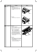
Push the bear
ing
to inside hole of base
bearing follow direction of arrow (Fig. 2
7
)
Pull the
bearing follow direction of arrow
(Fig. 2
8
)
2.
Atta
chment
1) Mounting bearing to the original position.
Base bearing
Bearing
(Fi
g
. 2
7
)
Base bearing
Bearing
(Fi
g
. 2
8
)
1
3
Heat exchanger
1.
Detachment
1)
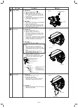
Recover the refrigerant gas.
2)
Remove the refrigerant pipe at indoor unit side.
3)
Carry out work of item 1 of
⑥
and
item 1 of
⑩
.
4)
Remove the heat exchanger sensor
(CN100 : TC1 sensor, Brown, 3P)
(CN101 : TC2 sensor, Black, 2P) and
(CN102 : TCJ sensor, Red, 2P)
connected to the control P.C. board and then
remove the lead wire from the clamp.
5)
Loosen the earth screw and then remove the
earth lead wire from the heat exchanger.
6)
Loosen the fixing screw
(Ø5/32"(4mm) x
0.4"(10mm) 4 pcs.)
and
then remove the heat
exchanger. (Fig. 2
9
)
2.
Atta
chment
1)
Tighten the fixing screw to the heat exchanger.
2)
Mount the earth l
ead wire
with the earth screw
to the heat exchanger.
3)
Connect the heat exchanger sensor (TC1,
TC2 and TCJ) to the control P.C. board and
then fix it as before with the clamp.
(Fig. 2
9
)
Earth screw
Heat exchanger
- 103 -


