48
4. Auxilliary boiler control
Isolate the electrical supply to the ESTIA system and remove the cover to the electrical box
in the hydro unit
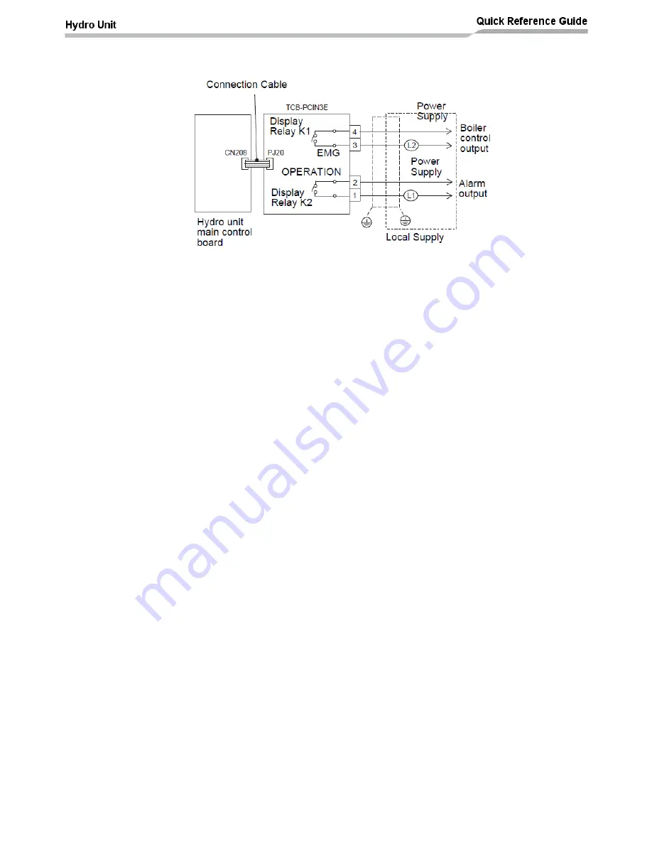
Connect the start signal for the auxillary boiler to terminals 3 & 4 (EMG) of the TCB-PCIN3E
option PCB as shown in the diagram above
Set DPSW 13_2 to ON. This enables the control for boiler output control
Replace the cover on the electrical box in the hydro unit and restore the electrical supply to
the ESTIA system
Set the following function codes to the required setting:
FC23: Sets the OAT where the boiler output is switched ON
FC3E: Allows the boiler output to be synchronised with the heat pump or to run as an
independent device
If FC3E is set to 0 then the boiler is synchronised with the heat pump. In this
condition the heat pump and the boiler will run at the same time. When the water
temperature, inside the hydro unit, reaches thermo OFF conditions then the heat
pump will STOP and the boiler output will turn OFF
If FC3E is set to 1 then the heat pump and the boiler will run as independent
devices. When the water temperature, inside the hydro unit, reaches thermo OFF
conditions then the heat pump will STOP. However with FC3E = 1 the boiler output
will remain ON. The temperature of the water, from the boiler, will be controlled by
the boilers’ own thermostat
FC5B: Sets the operating mode for the system when the boiler output is ON:
FC5B = 0: The heat
pump and the boiler will operate when OAT ≤ FC23
FC5B = 1: Boiler only operation (in this mode of operation the hydro unit pump will
continue to run)
FC5B = 2: Electric heater only operation (in this mode of operation the hydro unit
pump will continue to run)
FC5B = 3: Boiler only operation (in this mode of operation the hydro unit pump will
STOP and the boiler output will stay ON)


