background image

2.

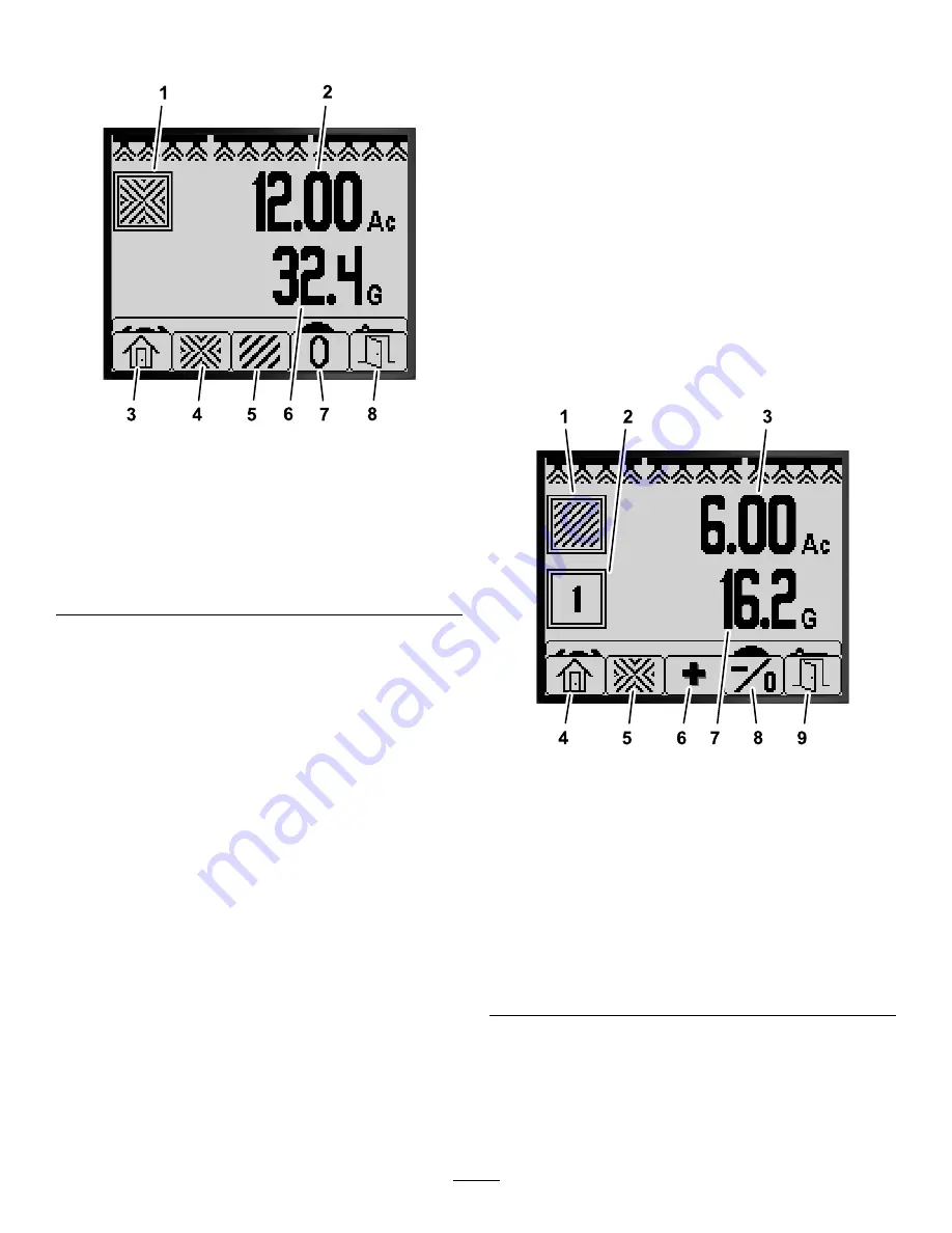
Press button 2 for the Total Area screen (

Figure

76

).

g194884

Figure 76

Total Area Screen

1.

Total area icon

5.

View Sub-Area screen

2.

Total area sprayed (acres)

6.

Total volume sprayed (US
gallons)

3.

Return to Home screen

7.

Reset total area and
volume sprayed.

4.

View Total Area screen

8.

Exit

3.

Use the InfoCenter buttons (

Figure 76

) to

perform the following actions:

Press button 1 to return to the Home screen.

Press button 2 to navigate to the Total Area
screen.

Press button 4 to reset total area and total
volume sprayed.

Press button 5 to exit the menu bar.

Using the Sub-Area Screen

Use an individual sub-area for each sprayer job at
your site. You can use up to 20 sub-areas to collect
sprayer information for the sprayer jobs at the site.

You can use information on the sub-area screen to
track the amount of area and amount of chemical
sprayed for each sprayer job for which you define
a sub-area.

Area and volume sprayed information accumulates
for the active sub-area in the sprayer system
memory until you reset it. Either press and hold
button 4 to reset the sub-area or reset the total
area and total volume information at the total-area
screen.

Note:

Resetting the total area and total volume

information at the total-area screen resets all

sub-area and sub-area volume information for
active and inactive sub-areas.

Note:

If the volume sprayed and area sprayed

data for a selected sub-area is cleared, the sprayer
system deducts that sub-area volume sprayed
and area sprayed quantity from the total volume
sprayed and total area sprayed data.

To make a different sub-area active, press and
release buttons 3 or 4 on the InfoCenter.

Important:

The number shown in the box

below the sub-area icon indicates the active
sub-area where area and volume information
being is collected.

If there is existing data in the active sub-area that
you do not need, reset area and volume sprayed
information for that sub-area.

1.

Navigate to the Sub-Area menu as follows:

g194883

Figure 77

Sub-Area Screen

1.

Sub-area icon

6.

Select the next sub-area

2.

Active sub-area

7.

Volume sprayed in the
active sub-area (US
gallons)

3.

Area sprayed in the active
sub-area (acres)

8.

Select the previous
sub-area; hold the button
to reset area and volume
sprayed for the active
sub-area.

4.

Return to Home screen

9.

Exit

5.

View Total Area screen

From the Home screen, press and hold
button 5 to open the menu bar and press
button 2 to select the Sub-Area screen
(

Figure 77

).

From the Total Area Screen, press and hold
button 5 to open the menu bar and press

27


Содержание Multi Pro 5800

Страница 1: ...ng the Sprayer 14 During Operation 26 InfoCenter Spray Area Screens 26 InfoCenter Advisories 28 InfoCenter Fault Codes 29 Maintenance 30 Service Screens 30 Diagnostics Screens 31 About Screens 32 Setu...

Страница 2: ...isplaying the corresponding icons that apply i e the parking brake is engaged the sprayer sections are on you are out of the seat etc Note The following figure is an example screen this screen shows a...

Страница 3: ...the parking brake is engaged Figure 1 Operator s Seat Indicator The operator seat indicator displays on the Home Screen when the operator is out of the seat Figure 1 Active Application Rate Boost Rat...

Страница 4: ...tage Setting the Active Rate Use the active rates option to set the sprayer preset rate to either rate 1 or rate 2 1 Press button 1 or 2 to navigate to the ACTIVE RATE option Figure 5 g191729 Figure 5...

Страница 5: ...uch as additional herbicide sprayed at an area of weeds Note While using the sprayer at the Home screen press and hold buttons 1 and 5 simultaneously to apply boost rate Boost is active only as long a...

Страница 6: ...set the Tank Volume Low Limit Low Limit Volume and Preset Agitation settings Setting the Tank Volume 1 Press button 1 or 2 to navigate to the TANK VOLUME option Figure 12 g191833 Figure 12 2 Press bu...

Страница 7: ...psi x 2 0 initial agitation preset pressure 5 5 bar 80 psi Record your calculation here 3 With the master section switch in the OFF position and the engine throttle set to the engine speed you intend...

Страница 8: ...cre Turf mph gallons 1000 ft SI metric kph liter hectare Note Changing the units of measure setting clears the tank volume entry and the preset Rate 1 and Rate 2 settings 3 Press button 5 to save the...

Страница 9: ...reen and return to the SETTINGS screen Figure 20 Setting Protection for Menus Note Refer to Changing PIN Settings Assessing the PIN Settings Sub menu page 10 for related information 1 Press buttons 1...

Страница 10: ...ring the PIN press button 5 Figure 24 Note Each time you press the same button to enter a PIN digit the number increases in value g034292 Figure 24 1 Digit 1 4 Digit 4 2 Digit 2 5 Enter PIN 3 Digit 3...

Страница 11: ...enter a PIN digit the number increases in value 4 At the enter old PIN screen press buttons 1 through 4 to enter your old PIN code and press button 5 when you complete the PIN Figure 24 Note The defau...

Страница 12: ...io warning for the machine 1 Press buttons 1 or 2 to navigate to the MUTE option Figure 30 g191890 Figure 30 2 Press button 4 to turn the audio indicator ON or OFF Figure 31 g191889 Figure 31 3 Press...

Страница 13: ...thers g191707 Figure 35 4 Press button 4 to reset the settings for the selected option Figure 35 5 Repeat steps 3 and 4 for other options that you want to reset Figure 35 6 Press button 5 to save your...

Страница 14: ...menu Figure 39 Note This screen displays and allows you to calibrate the flow meter input calibrate the speed sensor input perform a speed test and manually enter calculation data Flow Calibration Cus...

Страница 15: ...optional calibration after performing the 3 sprayer section calibration Note The calibration you perform for two sprayer sections is used whenever you spray with any combination of 2 sprayer sections...

Страница 16: ...e throttle to the FAST position Figure 43 and allow the engine to run for 10 minutes Important You must bring the hydraulic system to operating temperature before proceeding with the remaining flow ca...

Страница 17: ...switches as follows Note Refer to Preparing for the Flow Test page 15 Select the left center and right section switches for a 3 sprayer section calibration Important You must perform this calibration...

Страница 18: ...t the master section switch to the ON position Figure 47 2 Use the application rate switch to adjust the sprayer system pressure to approximately 276 kPa 40 psi refer to Figure 49 g192699 Figure 49 1...

Страница 19: ...container significantly impacts the accuracy of the sprayer calibration g193416 Figure 52 1 Highest point of the fluid surface curve do not measure here 3 Level surface 2 Lowest point of the fluid su...

Страница 20: ...lculation 1 Set the master section switch to the ON position Figure 53 g192853 Figure 53 2 Press button 2 to advance to begin the calibration calculation Figure 53 Note The InfoCenter displays the cal...

Страница 21: ...to the Calibrate screen Figure 58 Press button 2 to proceed to the calibration steps in Preparing the Sprayer Section s for the Catch Test page 17 Note You will set only the sprayer section switches...

Страница 22: ...an cancel the speed calibration by pressing button 5 A message displays confirming that you canceled the speed calibration g192423 Figure 62 4 Press button 2 to advance to the next step Figure 61 5 Ma...

Страница 23: ...ole of the machine ensure that the switches for the 3 section valves are in the OFF position g192356 g192354 Figure 66 1 Left section switch 3 Right section switch 2 Center section switch 3 Press butt...

Страница 24: ...4 Figure 69 5 Press button 5 to exit the Speed Calibration screen Figure 68 or Figure 69 6 Move the throttle to the SLOW position shut off the engine engage the parking brake and remove the ignition k...

Страница 25: ...ATE screen Figure 72 Using the Manual Cal Entry Use the manual cal entry screen to view the calibration values for 3 sprayer section boom 2 sprayer section boom 1 sprayer section boom and the speed Im...

Страница 26: ...gallons that you have sprayed across all areas since the total area and total area volume information was last reset You can use information on the total area screen to track the amount of area and am...

Страница 27: ...tting the total area and total volume information at the total area screen resets all sub area and sub area volume information for active and inactive sub areas Note If the volume sprayed and area spr...

Страница 28: ...curs there is a condition e g start prevent engine stopped an advisory code number a qualifier the cause of the advisory displayed and a display text what the advisory displays as text on the screen a...

Страница 29: ...lues Parameter status invalid data defaults used Booms Turned Off 802 Speed dropped Booms turned off stopped or moving too slowly GeoLink Configuration 902 GeoLink controller conflict GeoLink Configur...

Страница 30: ...mode Call your Authorized Toro Service Distributor 41 Sprayer pump control valve TEC controller electrical problem Call your Authorized Toro Service Distributor Maintenance Service Screens 1 To acces...

Страница 31: ...screen and return to the MAIN MENU screen Figure 82 Diagnostics Screens 1 To access the Diagnostics screen press buttons 1 or 2 on the Main Menu screen to navigate to the DIAGNOSTICS option Figure 83...

Страница 32: ...VIEWER entry Figure 86 3 Review the fault viewer for sprayer system generated faults Figure 87 Note If you see faults listed in the viewer contact your Authorized Toro Service Dealer g192032 Figure 8...

Страница 33: ...tons 1 or 2 to scroll the machine information screen the TEC controller information screen or the InfoCenter information screen Figure 89 4 Press button 5 to exit the ABOUT screen and return to the DI...

Страница 34: ...Notes...

Страница 35: ...Notes...

Страница 36: ......

Отзывы: