Preparing the Machine when
Spraying in the Manual Mode
1.
Fill the sprayer tank and fresh water tank; refer
to filling the spray tank and filling the fresh-water
tank procedures in the
Operator’s Manual
.
2.
As needed, configure the following optional
settings:
•
Optional: If you are using the
LOW LIMIT
INDICATOR
, enter the volume of chemical in
the sprayer tank; refer to
.
•
Optional: set the low limit indicator and the
low limit volume value for the tank; refer to
Setting the Low Limit Indicator (page 6)
and
Setting the Low Limit Volume Value (page 7)
.
Product Overview
Controls
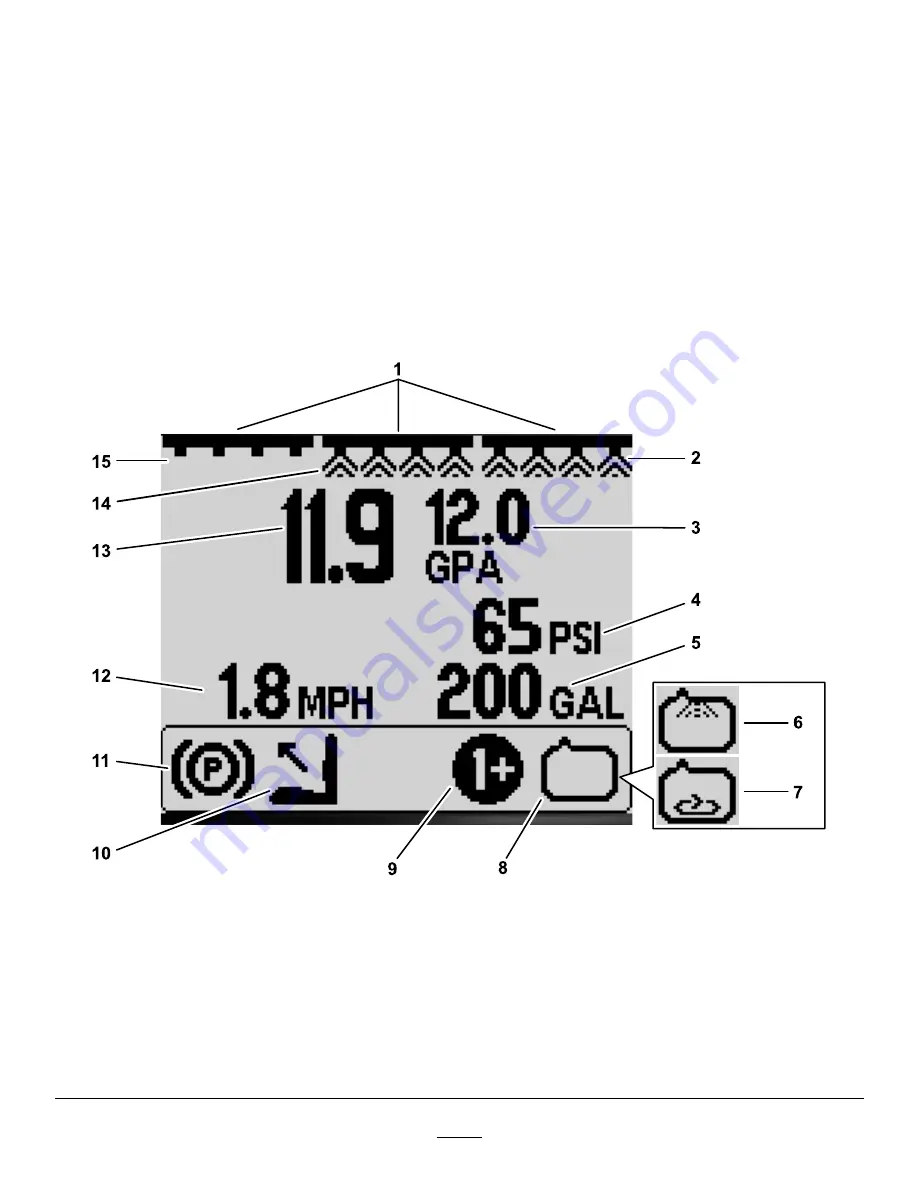
InfoCenter Home Screen
When you start the machine, the home screen
appears, displaying the corresponding icons that
apply (i.e., the parking brake is engaged, the sprayer
sections are on, you are out of the seat, etc.).
Note:
The following figure is an example screen;
this screen shows all the
potential
icons that could
appear on the screen while operating.
Refer to the following graphic for all of the icon
definitions (
g191986
Figure 1
1.
Master section-switch
indicator—O
N
5.
Tank-volume indicator (US
gallons shown)
9.
Active-application
rate/boost-rate
indicator—O
N
13.
Active-application rate (gpa
shown)
2.
Right section indicator—O
N
6.
Rinse-system
indicator—O
N
(optional
kit)
10.
Operator out of seat
14.
Center section
indicator—O
N
3.
Target-application rate (gpa
shown)
7.
Agitation indicator—O
N
11.
Parking-brake indicator
15.
Left section indicator—O
FF
4.
System-pressure indicator
(psi shown)
8.
Spray-pump indicator—O
N
12.
Vehicle-speed indicator
(mph shown)
2


