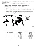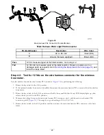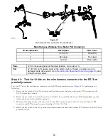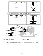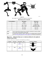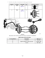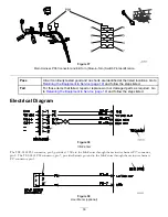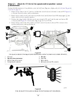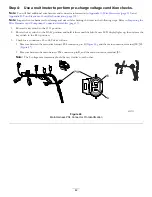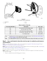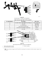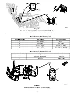
Main Harness P05 Connector
Pin Identification
Description
Wire Color
A
Voltage Out
Blue (BU)
B
Ground (harness supplied)
Black (BK)
C
5 Vdc In
Yellow (Y)
D
Not used
Not used
E
Not used
Not used
F
Not used
Not used
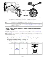
Figure 43
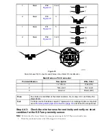
Main Harness P04 Connector
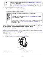
Pass
5 Vdc measured good at the listed location. Go to
Returning the Equipment to Service
(page 19)
and follow the steps listed.
Fail
5 Vdc did not measure good at the listed location. Go to step 4.2.
Step 4.2:
Check the wire harness for continuity and verify that there are no
short conditions of the speed-control potentiometer.
Note:
Inspect the wire harnesses for damage and wear while checking the items in the following steps. Refer to
Inspecting the Wire Harnesses and Component Connector Assemblies (page 13)
.
Disconnect the battery pack. Refer to
Disconnecting the Battery Pack (page 17)
.
Note:
Troubleshoot 1 circuit or component at a time. Disconnect or isolate each component or wire harness section
from the system before testing.
1.
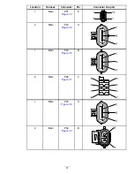
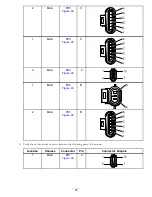
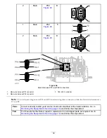
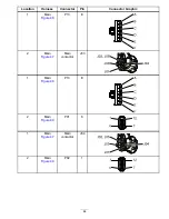
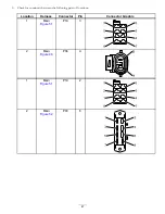
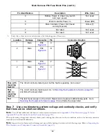
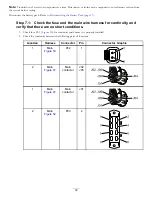
Check for continuity between the following pairs of locations:
Location
Harness
Connector
Pin
Connector Graphic
1
Main
P01
4
1
12
7
6
37
Содержание 04042
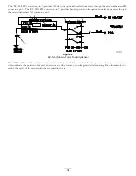
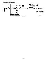
Страница 40: ...Electrical Diagram Figure 45 40 ...
Страница 69: ...Electrical Diagram Figure 67 CAN Bus Electrical Diagram 69 ...
Страница 87: ...Electrical Diagram Figure 81 87 ...


