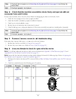
2.
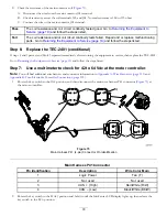
Rotate the key switch to the S
TART
position and hold it until the InfoCenter LCD display lights up, then release the
key switch to the R
UN
position.
3.
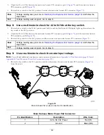
Check for 42 to 64 Vdc between the main wire harness P42 connector, pin 1 (
), and the main wire harness
P04 connector, pin B (
).
4.
Rotate the key to the O
FF
position, and then connect the main wire harness P42 connector (
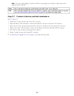
Pass
Voltage reading was good. Go to
Returning the Equipment to Service (page 19)
and follow
the steps listed.
Fail
Voltage reading was not good. Go to step 10.
Step 10:
Use a multimeter to check the wire harness for continuity and/or a
short condition for the motor.
Note:
You will find additional wire harness and connector information in
Appendix A: Wire Harnesses (page 113)
and
Appendix B: Toro Electronic Controller Connections (page 135)
.
Note:
Inspect the wire harness while checking the items in the following steps. Refer to
Inspecting the Wire Harnesses and
Component Connector Assemblies (page 13)
.
Note:
Troubleshoot 1 circuit or component at a time. Disconnect or isolate each component or wire harness section from
the system before testing.
Disconnect the battery pack. Refer to
Disconnecting the Battery Pack (page 17)
.
Step 10.1:
Check the motor wire harness for continuity and/or a short
condition.
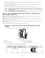
1.
Check the F1-1 fuse for continuity and ensure it is properly installed.
4
g030799
2
3
1
Figure 77
1.
Open slot
3.
Fuse F1-2 (3 amp/80 volt)
2.
Fuse F1-3 (3 amp/80 volt)
4.
Fuse F1-1 (30 amp/80 volt)
2.
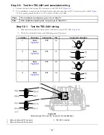
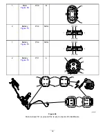
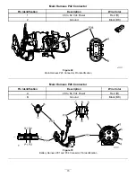
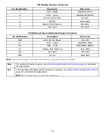
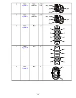
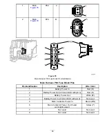
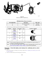
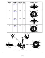
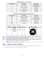
Check for continuity between the following pairs of locations:
Location
Harness
Connector
Pin
Connector Graphic
1
Main
P42
1
1
2
81
Содержание 04042
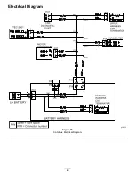
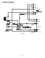
Страница 40: ...Electrical Diagram Figure 45 40 ...
Страница 69: ...Electrical Diagram Figure 67 CAN Bus Electrical Diagram 69 ...
Страница 87: ...Electrical Diagram Figure 81 87 ...

