1
Main
P02
7 or 8
1
12
7
6
2
Main
P43
3
1
3
1
Main
P01
5
1
12
7
6
2
Main
P02
7 or 8
1
12
7
6
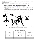
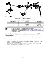
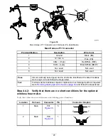
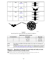
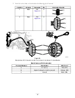
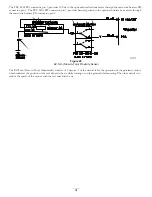
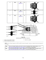
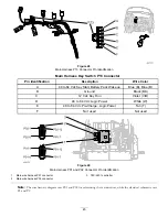
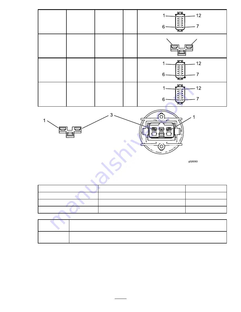
Figure 35
Main Harness P43 Connector and Wireless Hour Meter Pin Identification
Main Harness P43 Connector
Pin Identification
Description
Wire Color
1
12 Vdc In
Pink (PK)
2
Not used
Not used
3
Ground
Black (BK)
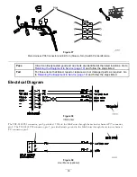
Pass
No shorts are identified at the listed locations. Go to step 4.4.3 and follow the
steps listed.
Fail
For those items that failed, repair or replace worn or damaged parts as required.
Go to
Returning the Equipment to Service (page 19)
and follow the steps listed.
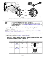
Step 4.4.3:
Check the wire harness for continuity and verify no short
condition for the EZ-Turn proximity sensor.
Note:
Refer to the
eFlex Service Manual
for component testing of the EZ-Turn switch and sensor.
1.
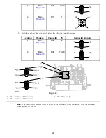
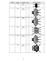
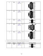
Check for continuity between the following pairs of locations:
30
Содержание 04042
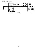
Страница 40: ...Electrical Diagram Figure 45 40 ...
Страница 69: ...Electrical Diagram Figure 67 CAN Bus Electrical Diagram 69 ...
Страница 87: ...Electrical Diagram Figure 81 87 ...

