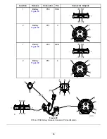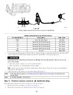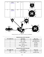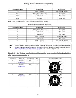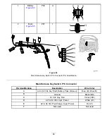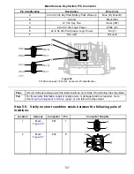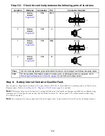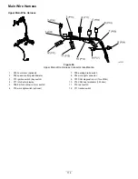
Figure 85
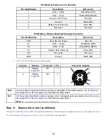
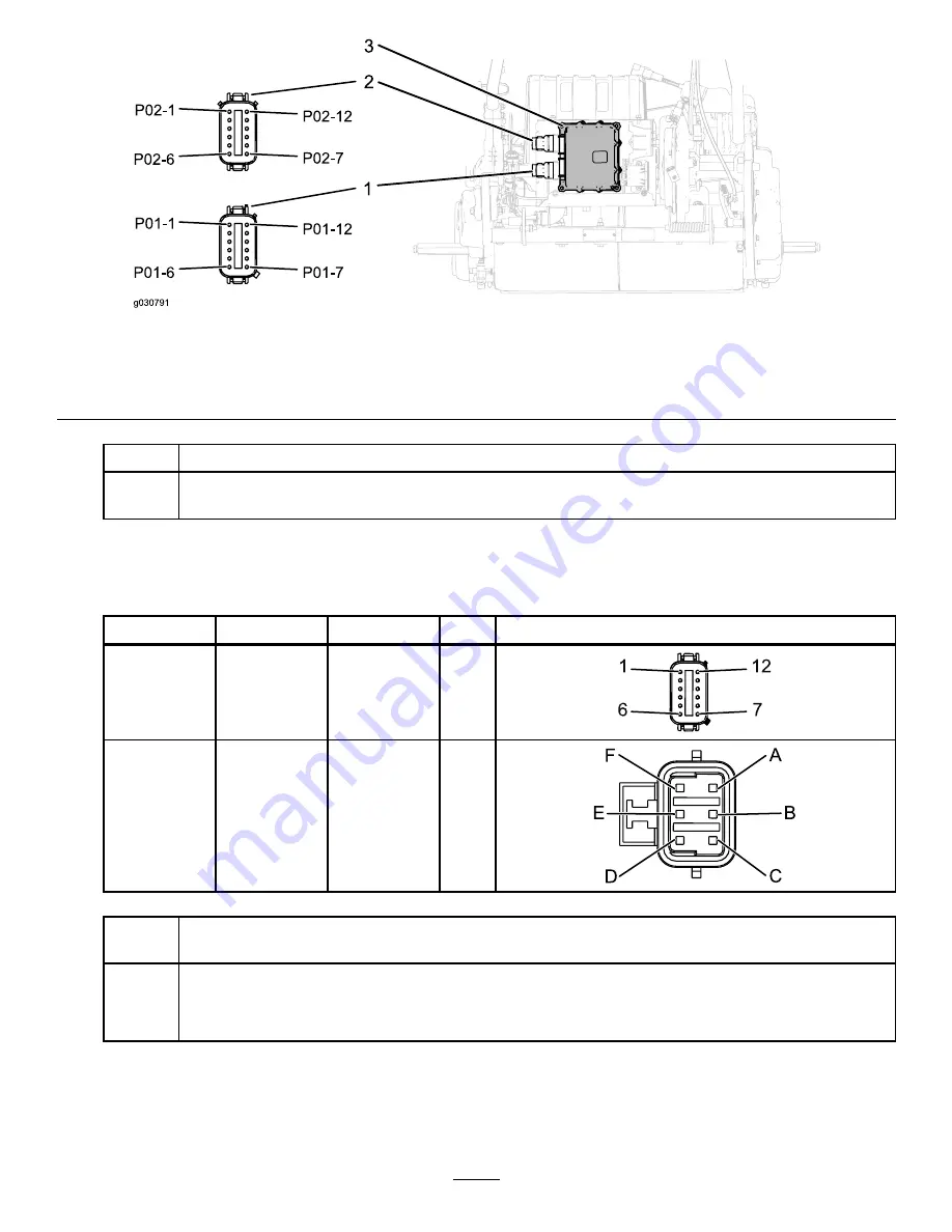
P01 Main Harness TEC–2401 Connector Pin Identification
1.
Main wire harness P02 connector
3.
TEC-2401 controller
2.
Main wire harness P01 connector
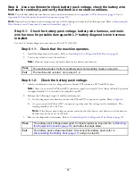
Pass
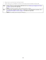
Circuit continuity tested good at the listed locations. Go to Step 6.5 and follow the steps listed.
Fail
For those items that failed, repair or replace the worn or damaged parts as required. Go to
Returning the Equipment to Service (page 19)
and follow the steps listed.
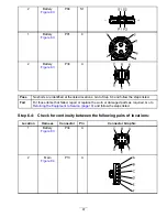
Step 6.5:
Verify that no short conditions exist between the following pairs
of locations:
Location
Harness
Connector
Pin
Connector Graphic
1
Main
P01
1
1
12
7
6
2
Main
P02
7 or 8
F
E
D
A
B
C
Pass
No shorts are identified at the listed locations. Go to
Returning the Equipment to Service
(page 19)
and follow the steps listed.
Fail
For those items that failed, repair or replace the worn or damaged parts as required. Go to
Returning the Equipment to Service (page 19)
and follow the steps listed.
Note:
Do not replace the battery pack unless the fault repeats.
99
Содержание 04042
Страница 40: ...Electrical Diagram Figure 45 40 ...
Страница 69: ...Electrical Diagram Figure 67 CAN Bus Electrical Diagram 69 ...
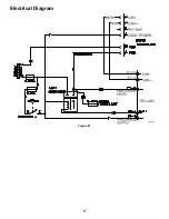
Страница 87: ...Electrical Diagram Figure 81 87 ...

