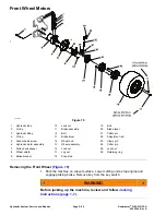
Removing the Rear Wheel Motor (
) (continued)
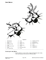
2. Jack up the rear of equipment enough to allow the removal of the rear wheel.
3. Remove the rear wheel assembly from the machine; refer to
Rear Fork and Wheel (page 7–14)
.
4. Thoroughly clean the hydraulic hose ends and rear wheel motor fittings to
prevent hydraulic system contamination.
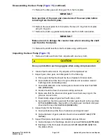
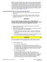
WARNING
Before disconnecting or performing any work on the hydraulic
system, all pressure in the system must be relieved. See
Hydraulic System Pressure (page 5–3)
.
5. Disconnect the hydraulic hoses from fittings on wheel motor. Plug the hose
openings to prevent contamination.
6. Remove four (4) socket head screws and lock nuts that secure rear wheel
motor to rear fork. Remove the wheel motor with wheel hub attached from
the rear fork.
7. Secure the wheel hub in a vise. Loosen but do not remove lock nut that
secures the wheel hub to wheel motor.
IMPORTANT
DO NOT hit wheel hub, wheel hub puller or wheel motor with a
hammer during wheel hub removal or installation. Hammering may
cause damage to the wheel motor.
8. Using hub puller (see
Special Tools (page 2–13)
), loosen wheel hub from
wheel motor.
9. Remove the wheel hub and motor from vise. Remove the lock nut and wheel
hub from motor shaft. Locate and retrieve the woodruff key.
10. If hydraulic fittings are to be removed from the wheel motor, mark fitting
orientation to allow correct assembly. Discard the O−rings from removed
fittings.
Installing the Rear Wheel Motor (
1. If fittings were removed from the rear wheel motor, lubricate and place new
O−rings onto fittings. Install the fittings into motor openings using marks
made during the removal process to properly orientate fittings. Tighten
fittings (see
Installing the Hydraulic Fittings (SAE Straight Thread O-Ring
).
2. Thoroughly clean the wheel motor shaft and wheel hub taper.
3. Lock the wheel hub in a vise. Install woodruff key into the wheel motor
shaft. Slide the motor shaft into hub and secure with lock nut. Torque lock
nut from
345 to 372 N·m (255 to 275 ft−lb)
. Remove the wheel motor and
hub from vise.
4. Position the wheel motor with wheel hub attached to the rear fork. Secure the
rear wheel motor to rear fork with four (4) socket head screws and lock nuts.
Reelmaster
®
3100-D/3105-D
Page 5–99
Hydraulic System: Service and Repairs
20252SL Rev A
Содержание 03200 Reelmaster 3100-D
Страница 4: ...NOTES NOTES Page 4 Reelmaster 3100 D 3105 D 20252SL Rev A ...
Страница 6: ...g341979 Figure 1 Preface Page 6 Reelmaster 3100 D 3105 D 20252SL Rev A ...
Страница 10: ...Preface Page 10 Reelmaster 3100 D 3105 D 20252SL Rev A ...
Страница 20: ...Safety Safety and Instructional Decals Page 1 10 Reelmaster 3100 D 3105 D 20252SL Rev A ...
Страница 44: ...Specifications and Maintenance Special Tools Page 2 24 Reelmaster 3100 D 3105 D 20252SL Rev A ...
Страница 88: ...g344528 Figure 28 Hydraulic System Hydraulic Schematic Page 5 12 Reelmaster 3100 D 3105 D 20252SL Rev A ...
Страница 89: ...g344526 Figure 29 Reelmaster 3100 D 3105 D Page 5 13 Hydraulic System Hydraulic Schematic 20252SL Rev A ...
Страница 198: ...g345756 Figure 95 Hydraulic System Service and Repairs Page 5 122 Reelmaster 3100 D 3105 D 20252SL Rev A ...
Страница 204: ...g345782 Figure 99 Hydraulic System Service and Repairs Page 5 128 Reelmaster 3100 D 3105 D 20252SL Rev A ...
Страница 224: ...Hydraulic System Service and Repairs Page 5 148 Reelmaster 3100 D 3105 D 20252SL Rev A ...
Страница 308: ...Wheels Brakes and Chassis Service and Repairs Page 7 30 Reelmaster 3100 D 3105 D 20252SL Rev A ...
Страница 376: ...Universal Groomer Optional Service and Repairs Page 9 22 Reelmaster 3100 D 3105 D 20252SL Rev A ...
Страница 382: ...Page A 6 20252SL Rev A Reelmaster 3100 D 3105 D Drawing 122 1522 Rev A Sheet 1 of 1 Electrical Schematic g346835 ...
Страница 383: ...Reelmaster 3100 D 3105 D Drawing 122 1523 Rev B Sheet 1 of 2 20252SL Rev A Page A 7 Wire Harness Drawing CV g346834 ...
Страница 384: ...Page A 8 20252SL Rev A Reelmaster 3100 D 3105 D Drawing 122 1523 Rev A Sheet 2 of 2 Wire Harness Drawing g346833 ...
Страница 385: ......

