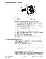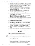
Assembling the Gear Pump (
) (continued)
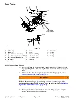
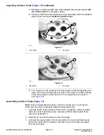
4. Install new pressure seal and back−up gasket into both new wear plates.
The flat section in the middle of the back−up gasket must face away from the
wear plate inside the seal.
5. Install wear plate into the gear pocket with the pressure seal and back−up
gasket against the front plate. Make sure mid section cut−away of the wear
plate is on the suction side of the pump.
6. Dip drive gear and front idler gear into clean hydraulic oil. Install gear shafts
into the front plate bushings so that the gears set inside the gear pockets.
7. Install new O−ring into the groove of the adapter plate on the side with the
bushings below the surface.
8. Align marker line on the body and adapter plate. Install adapter plate onto
the body and gear shafts.
9. Install second new O−ring to the other side of the adapter plate.
10. Coat key lightly with petroleum jelly to hold it in place. Install key into the
slot in the drive gear shaft.
11. Align marker line on back body and adapter plate. Install body onto adapter
plate and drive gear shaft.
IMPORTANT
Do not dislodge seals during installation.
12. Install the wear plate into the gear pocket of back body with the pressure
seal and back−up gasket against the adapter plate. Make sure mid section
cut−away of the wear plate is on the suction side of the pump.
13. Lubricate the back gear with clean hydraulic oil. Install the gear onto the
drive gear shaft and key.
14. Lubricate the back idler gear with clean hydraulic oil. Install the idler gear into
the gear pocket of back body and the adapter plate.
15. Install new O−ring into the groove of the back plate.
16. Align marker line on the back plate and body. Install back plate onto the
body and gear shafts.
17. Secure pump together with cap screws and new washers on cap screws
external of the flange cavity. Torque cap screws in a criss−cross pattern
from
34 to 38 N·m (25 to 28 ft−lb)
.
Reelmaster
®
3100-D/3105-D
Page 5–95
Hydraulic System: Service and Repairs
20252SL Rev A
Содержание 03200 Reelmaster 3100-D
Страница 4: ...NOTES NOTES Page 4 Reelmaster 3100 D 3105 D 20252SL Rev A ...
Страница 6: ...g341979 Figure 1 Preface Page 6 Reelmaster 3100 D 3105 D 20252SL Rev A ...
Страница 10: ...Preface Page 10 Reelmaster 3100 D 3105 D 20252SL Rev A ...
Страница 20: ...Safety Safety and Instructional Decals Page 1 10 Reelmaster 3100 D 3105 D 20252SL Rev A ...
Страница 44: ...Specifications and Maintenance Special Tools Page 2 24 Reelmaster 3100 D 3105 D 20252SL Rev A ...
Страница 88: ...g344528 Figure 28 Hydraulic System Hydraulic Schematic Page 5 12 Reelmaster 3100 D 3105 D 20252SL Rev A ...
Страница 89: ...g344526 Figure 29 Reelmaster 3100 D 3105 D Page 5 13 Hydraulic System Hydraulic Schematic 20252SL Rev A ...
Страница 198: ...g345756 Figure 95 Hydraulic System Service and Repairs Page 5 122 Reelmaster 3100 D 3105 D 20252SL Rev A ...
Страница 204: ...g345782 Figure 99 Hydraulic System Service and Repairs Page 5 128 Reelmaster 3100 D 3105 D 20252SL Rev A ...
Страница 224: ...Hydraulic System Service and Repairs Page 5 148 Reelmaster 3100 D 3105 D 20252SL Rev A ...
Страница 308: ...Wheels Brakes and Chassis Service and Repairs Page 7 30 Reelmaster 3100 D 3105 D 20252SL Rev A ...
Страница 376: ...Universal Groomer Optional Service and Repairs Page 9 22 Reelmaster 3100 D 3105 D 20252SL Rev A ...
Страница 382: ...Page A 6 20252SL Rev A Reelmaster 3100 D 3105 D Drawing 122 1522 Rev A Sheet 1 of 1 Electrical Schematic g346835 ...
Страница 383: ...Reelmaster 3100 D 3105 D Drawing 122 1523 Rev B Sheet 1 of 2 20252SL Rev A Page A 7 Wire Harness Drawing CV g346834 ...
Страница 384: ...Page A 8 20252SL Rev A Reelmaster 3100 D 3105 D Drawing 122 1523 Rev A Sheet 2 of 2 Wire Harness Drawing g346833 ...
Страница 385: ......


