


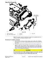


Assembling the Drive System
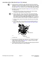
1. Install drive shaft if it was removed:
IMPORTANT
If rear roller brush drive is on left side of cutting unit, drive shaft has
left hand threads and can be identified by a groove on the flange.
If the rear roller brush drive is on right side of cutting unit, drive
shaft has right hand threads and does not have a groove on the
flange (
A. Apply Loctite #243 (or equivalent) to threads of drive shaft. Thread drive
shaft into cutting reel and torque from
115 to 128 N·m (85 to 95 ft-lb)
.
B. Make sure that the O-ring is placed on inner flange of drive housing.
C. Position housing to cutting unit side plate and secure to cutting unit with
two (2) socket head screws.
D. Make sure that grommet groove is correctly seated on flange in drive
housing bore.
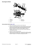
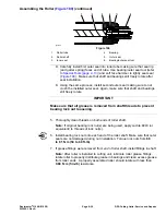
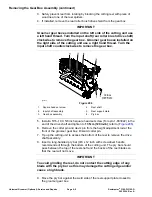
2. Assemble roller brush components using
as a guide.
A. During assembly, apply Loctite #243 (or equivalent) to threads of
fasteners and torque fasteners as shown in
B. Apply a light coating of grease to inner diameter of the grommet in drive
bearing housing before installing brush plate.
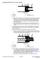
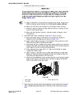
C. Brush plate should be installed so that idler pulley assembly is toward the
bottom of the plate. Also, the shoulder bolt (item 15) should not clamp the
brush plate to the drive housing during assembly.
D. When installing drive pulley (item 17), make sure that tabs on pulley
engage slot in drive shaft.
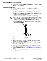
E. Idler arm (item 7) should be free to rotate after assembly to brush plate.
Make sure that idler spring is installed so that it can rotate the idler arm
and pulley and apply tension to the drive belt.
F. After drive belt installation, make sure that the ribs on the belt are properly
seated in the grooves of both the drive and driven pulleys and that the
belt is in the center of the idler pulley.
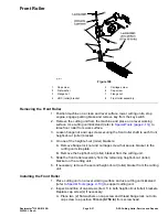
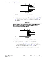
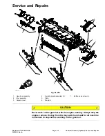
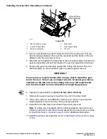
g214810
Figure 202
1.
Driven pulley
3.
Pulley alignment tool
2.
Drive pulley
3. After assembly (including drive belt installation), check alignment of pulleys
with a straight edge placed along the outer face of the drive pulley (
Reelmaster
®
3100-D/3105-D
Page 8–45
DPA Cutting Units: Service and Repairs
20252SL Rev A
Содержание 03200 Reelmaster 3100-D
Страница 4: ...NOTES NOTES Page 4 Reelmaster 3100 D 3105 D 20252SL Rev A ...
Страница 6: ...g341979 Figure 1 Preface Page 6 Reelmaster 3100 D 3105 D 20252SL Rev A ...
Страница 10: ...Preface Page 10 Reelmaster 3100 D 3105 D 20252SL Rev A ...
Страница 20: ...Safety Safety and Instructional Decals Page 1 10 Reelmaster 3100 D 3105 D 20252SL Rev A ...
Страница 44: ...Specifications and Maintenance Special Tools Page 2 24 Reelmaster 3100 D 3105 D 20252SL Rev A ...
Страница 88: ...g344528 Figure 28 Hydraulic System Hydraulic Schematic Page 5 12 Reelmaster 3100 D 3105 D 20252SL Rev A ...
Страница 89: ...g344526 Figure 29 Reelmaster 3100 D 3105 D Page 5 13 Hydraulic System Hydraulic Schematic 20252SL Rev A ...
Страница 198: ...g345756 Figure 95 Hydraulic System Service and Repairs Page 5 122 Reelmaster 3100 D 3105 D 20252SL Rev A ...
Страница 204: ...g345782 Figure 99 Hydraulic System Service and Repairs Page 5 128 Reelmaster 3100 D 3105 D 20252SL Rev A ...
Страница 224: ...Hydraulic System Service and Repairs Page 5 148 Reelmaster 3100 D 3105 D 20252SL Rev A ...
Страница 308: ...Wheels Brakes and Chassis Service and Repairs Page 7 30 Reelmaster 3100 D 3105 D 20252SL Rev A ...
Страница 376: ...Universal Groomer Optional Service and Repairs Page 9 22 Reelmaster 3100 D 3105 D 20252SL Rev A ...
Страница 382: ...Page A 6 20252SL Rev A Reelmaster 3100 D 3105 D Drawing 122 1522 Rev A Sheet 1 of 1 Electrical Schematic g346835 ...
Страница 383: ...Reelmaster 3100 D 3105 D Drawing 122 1523 Rev B Sheet 1 of 2 20252SL Rev A Page A 7 Wire Harness Drawing CV g346834 ...
Страница 384: ...Page A 8 20252SL Rev A Reelmaster 3100 D 3105 D Drawing 122 1523 Rev A Sheet 2 of 2 Wire Harness Drawing g346833 ...
Страница 385: ......