Installation and Operational Instructions for
ROBA-stop
®
-Z Type 892.101.0
Size 125
(E073 01 046 000 4 EN)
18/05/2022 TK/HW/SU
Chr. Mayr GmbH + Co. KG
Eichenstraße 1, D-87665 Mauerstetten, Germany
Phone: +49 8341 804-0, Fax: +49 8341 804-421
Page 14 of 16
www.mayr.com
, E-Mail:
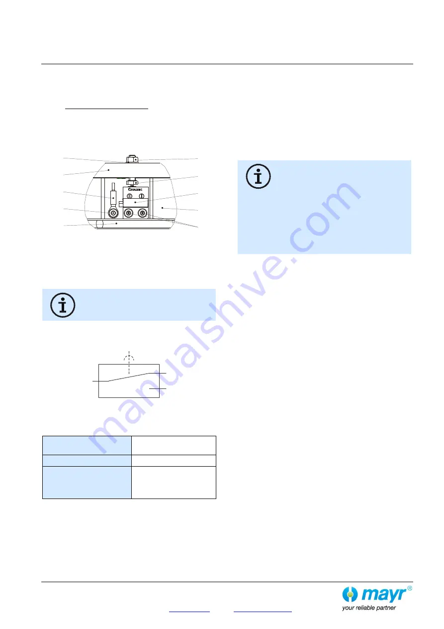
Release Monitoring
The brakes are supplied with manufacturer-side installed and
adjusted release monitoring device.
The microswitch (11.1) emits a signal for every brake condition
change: "brake opened or brake closed"
The customer is responsible for a signal evaluation of both
conditions.
From the point at which the brake is energized, a time span of
three times the separation time must pass before the switch
signal on the release monitoring is evaluated.
Fig. 10
Function
When the magnetic coil (2.1) is energized in the brake body (2),
the armature disk (14) is attracted to the brake body (2), the
microswitch (11.1) emits a signal, the brake is released.
When actuating the hand release (18), a
switching signal of the release monitoring
device (11) cannot be guaranteed.
Microswitch Wiring Diagram:
Microswitch Specification
Characteristic values for
measurement:
250 V~ / 3 A
Minimum switching power:
12 V, 10 mA DC-12
Recommended switching
power:
for maximum lifetime
and reliability
24 V, 10...50 mA
DC-12
DC-13 with freewheeling
diode!
Usage category acc. IEC 60947-5-1:
DC-12 (resistance load), DC-13 (inductive load)
Customer-side Inspection after Attachment
For customer-side connection as NO contact.
Brake de-energized
Signal "OFF",
Brake energized
Signal “ON”
For customer-side connection as NC contact.
Brake de-energized
Signal “ON”,
Brake energized
Signal “OFF”
Microswitches cannot be guaranteed fail-safe.
Therefore, please ensure appropriate access
for replacement or adjustment.
The switching contacts are designed so that
they can be used for both small switching
powers and medium ones. However, after
switching a medium switching power, small
switching powers are no longer reliably
possible.
In order to switch inductive, capacitive and non-
linear loads, please use the appropriate
protection circuit to protect against electric arcs
and unpermitted loads!
11.5
2
11.1
11.2
11.3
11.4
14
20
21/22
5
1
4
2
COM contact
Black connection
NC contact
Grey connection
Connection when
brake closed
NO contact
Blue connection
Connection when
brake released
Содержание TW45C
Страница 1: ...OPERATING MANUAL TW45C Drive 06 2022 6231003860...
Страница 86: ......
Страница 140: ...PP0099019030 AFG 000 00 FR 13 07 2020 HEIMERDING D Ausdruck unterliegt nicht dem nderungsdienst...
Страница 145: ...145 TK Elevator BA TW45C 6231003860 06 2022...
Страница 146: ...146 TK Elevator BA TW45C 6231003860 06 2022...
Страница 147: ...147 TK Elevator BA TW45C 6231003860 06 2022...


