Section 16: Data Transfer & Using 3
rd
Party Devices
T
ieline
T E C H N O L O G Y
Page 143
individually routed between two nodes (in our case two codecs) over shared LAN
and WAN connections.
Packet switching optimizes the use of bandwidth over computer and wireless
networks by dividing data streams into packets with destination addresses
embedded within them. In this way packets are routed through ISP routing tables
to find the best route to their destinations.
The exact form of a packet is determined by the protocol a network is using.
Packets are generally split into three parts which include:
A Header: This section contains instructions about the data contained
within the packet;
The Payload: This contains the actual data that is being sent to the
destination; and
A Trailer (Footer): This tells the receiving device that it has received
the entire packet and it may also contain error checking information
(used to send a packet resend request if a packet is corrupted).
16.5.
The OSI Model Explained
To assist in understanding the operation of session data within
T
ieline
codecs
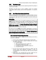
following is a diagram of the OSI model of computer network protocol design. In
the table below, the functions of the protocol are divided into layers to describe
each element individually.
The OSI Model Explained
Data Unit
Layer
Function
Layer 7: Application
End user processes to
application
Layer 6: Presentation Data representation/encryption
Application Data
Layer 5: Session
Establish, manage and terminate
communication.
Segments Layer 4: Transport
End-to-end data transfer, error
recovery and flow control (The
TCP & UDP protocols are used
on the Internet).
Packets
Layer 3: Network
Switching and routing (IP)
Frames
Layer 2: Data link
Physical addressing (i.e. MAC &
LLC)
Data
Transport
Bits
Layer 1: Physical
Hardware providing the ability to
send and receive data.
Table 7: The OSI Model Explained
This model is roughly adhered to throughout the IT industry and it is important to
recognize that each layer only uses the functions of the layer below it and only
performs services for the layer above it. The implementation of several layers is
often referred to as a ‘stack’.
It is appropriate to now explain the Session Layer in some more detail, as well as
the attributes of session data and how it is sent between two codecs.
Содержание i-Mix G3
Страница 41: ...Section 7 Quick Start Tieline Page 41 T E C H N O L O G Y 7 3 5 3G Wizard Figure 12 3G Wizard...
Страница 42: ...Section 7 Quick Start Tieline Page 42 T E C H N O L O G Y 7 3 6 New X 21 Wizard Figure 13 X 21 Menu Wizard...
Страница 116: ...Section 15 Operation of your Codec Tieline T E C H N O L O G Y Page 116 Figure 29 Menu Submenus...
Страница 119: ...Section 15 Operation of your Codec Tieline T E C H N O L O G Y Page 119 Figure 30 Configuration Submenu Items...
Страница 344: ...Appendix 1 Connector Wiring Tieline T E C H N O L O G Y Page 344 Appendix 1 10 CAN Cable Wiring Configuration...
Страница 350: ...Appendix 5 Codec Specifications Tieline T E C H N O L O G Y Page 350 Appendix 5 Codec Specifications...

