Section 17: Relay and Control Port Operation
T
ieline
T E C H N O L O G Y
Page 152
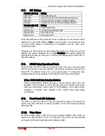
these cases a local power supply should be connected to the CAN 8+8. This
should be 9 volts DC, 500mA.
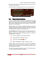
An external relay box is connected via the
CAN
port on the rear of the codec.
Figure 35: The Rear View of a CAN 8+8 External Relay Box
17.2.
Cabling and Operation Distances
A number of factors determine the maximum length. Firstly, there is the CAN
spec itself. This specifies a maximum length of 130m @ 500Kbps (the rate
T
ieline
codecs use). The second factor, which is often the limiting one, is the voltage
drop in the cable. Cable types, thickness, quality and length will all determine any
limitations in a unit’s performance.
Shielded dual twisted pair cables are recommended. Where cable runs are long
and master power source is being used, heavier conductors will be required.
Screw terminal plugs are provided to allow for easy on site wiring. These can be
hot plugged without any impact upon a unit’s performance.
In general,
T
ieline
recommends that the relay box should operate effectively on a
cable of 0.5 meters up to a maximum length of 75 meters from the codec.
Distances greater than this could be achievable. Following is a formula for
calculating maximum cable length:
V in(min) at relay box = 8V (minimum input voltage);
I (peak) at relay box = 250mA (peak current);
V out (min) at TLM600 (
i
-
Mix
G
3
) = 11V;
Max DC resistance (DCR) of cable = (11-8)/0.25 = 12 ohms.
Typically, 24AWG CAT5 cable has a DCR of about 0.095 ohms/meter.
Therefore, maximum length = (12/0.095)/2; dividing by 2 accounts for the
return path as well. In this example, the maximum theoretical length using this
cable’s specifications is about 63m.
A CAN cable wiring diagram is available in Appendix 1 of this reference manual.
This section is titled CAN Cable Wiring Configuration.
Содержание i-Mix G3
Страница 41: ...Section 7 Quick Start Tieline Page 41 T E C H N O L O G Y 7 3 5 3G Wizard Figure 12 3G Wizard...
Страница 42: ...Section 7 Quick Start Tieline Page 42 T E C H N O L O G Y 7 3 6 New X 21 Wizard Figure 13 X 21 Menu Wizard...
Страница 116: ...Section 15 Operation of your Codec Tieline T E C H N O L O G Y Page 116 Figure 29 Menu Submenus...
Страница 119: ...Section 15 Operation of your Codec Tieline T E C H N O L O G Y Page 119 Figure 30 Configuration Submenu Items...
Страница 344: ...Appendix 1 Connector Wiring Tieline T E C H N O L O G Y Page 344 Appendix 1 10 CAN Cable Wiring Configuration...
Страница 350: ...Appendix 5 Codec Specifications Tieline T E C H N O L O G Y Page 350 Appendix 5 Codec Specifications...

