


Section 17: Relay and Control Port Operation
T
ieline
T E C H N O L O G Y
Page 154
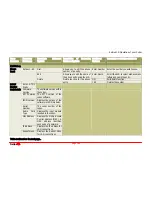
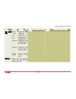
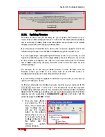
17.7.
DIP Settings
Function (Sw 2,1)
Setting
OFF, OFF
First CAN 8+8 unit
OFF, ON
Second CAN 8+8 unit (future software feature)
ON, OFF
Third CAN 8+8 unit (future software feature)
ON, ON
Fourth CAN 8+8 unit (future software feature)
Function (Sw 4,3)
Setting
Switch 3 Off
Pulse Relay Mode
Switch 3 On
Continuous On Relay Mode
Switch 4 Off
Piezo Alarm Off
Switch 4 On
Piezo Alarm On
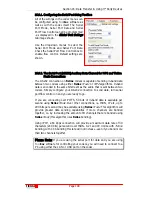
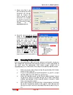
It may be necessary to set a particular mode of operation for the desired control
system when used with different
T
ieline
codec products. This should be done
once the control system is determined in consultation with the main codec
operation manual.
Normally, one CAN 8+8 will communicate with another one at the end of a link
between two codecs. Please see the
Tool
Box
Functions
menu section within this
manual about setting up codec User Functions and assigning the
SOFTKEY
or
HOTKEY
buttons.
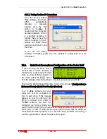
17.8.
CMOS Relay Operational Mode
As mentioned, the CMOS relays can be set to work in two ways. They can pulse
ON for one second or they can stay ON until another command is sent to turn
them OFF. The default mode is for a one second pulse. To change the relay
operational mode, make changes to DIP Switch 3 as per the previous table.
17.8.1.
CMOS Solid State Relay Specifications
These semiconductor devices provide a circuit closure when they are
activated. They are rated to 350 volts peak across the contact closure and
they have a maximum current rating of 120 milliamps. The contact closure
resistance is typically 18
Ω
. (Related Topic: CMOS Solid State Relay
Connectors)
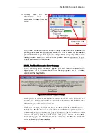
17.9.
Front Panel LED Indicators
The LED’s on the front panel of the unit indicate the state of the relays and
inputs. They also indicate a connection problem on the CAN buss by scanning
back and forth.
17.10.
Piezo Alarm
An internal piezo alarm is fitted to act as an audible indicator when either an
input or an output function occurs. The default for this is off. It can be activated
by changing DIP switch 4 settings per the table provided.
Содержание i-Mix G3
Страница 41: ...Section 7 Quick Start Tieline Page 41 T E C H N O L O G Y 7 3 5 3G Wizard Figure 12 3G Wizard...
Страница 42: ...Section 7 Quick Start Tieline Page 42 T E C H N O L O G Y 7 3 6 New X 21 Wizard Figure 13 X 21 Menu Wizard...
Страница 116: ...Section 15 Operation of your Codec Tieline T E C H N O L O G Y Page 116 Figure 29 Menu Submenus...
Страница 119: ...Section 15 Operation of your Codec Tieline T E C H N O L O G Y Page 119 Figure 30 Configuration Submenu Items...
Страница 344: ...Appendix 1 Connector Wiring Tieline T E C H N O L O G Y Page 344 Appendix 1 10 CAN Cable Wiring Configuration...
Страница 350: ...Appendix 5 Codec Specifications Tieline T E C H N O L O G Y Page 350 Appendix 5 Codec Specifications...