The screen content changes with operational state, depending on whether
the unit is:
• in startup mode, as shown in “Startup Mode”
• in working mode, as shown in Figure 4-8 above
• in standby mode, as explained in “Standby Mode”
• in idle mode, as explained in “Idle Mode”
• running UV Disinfection, as explained in “Running UV Disinfection”
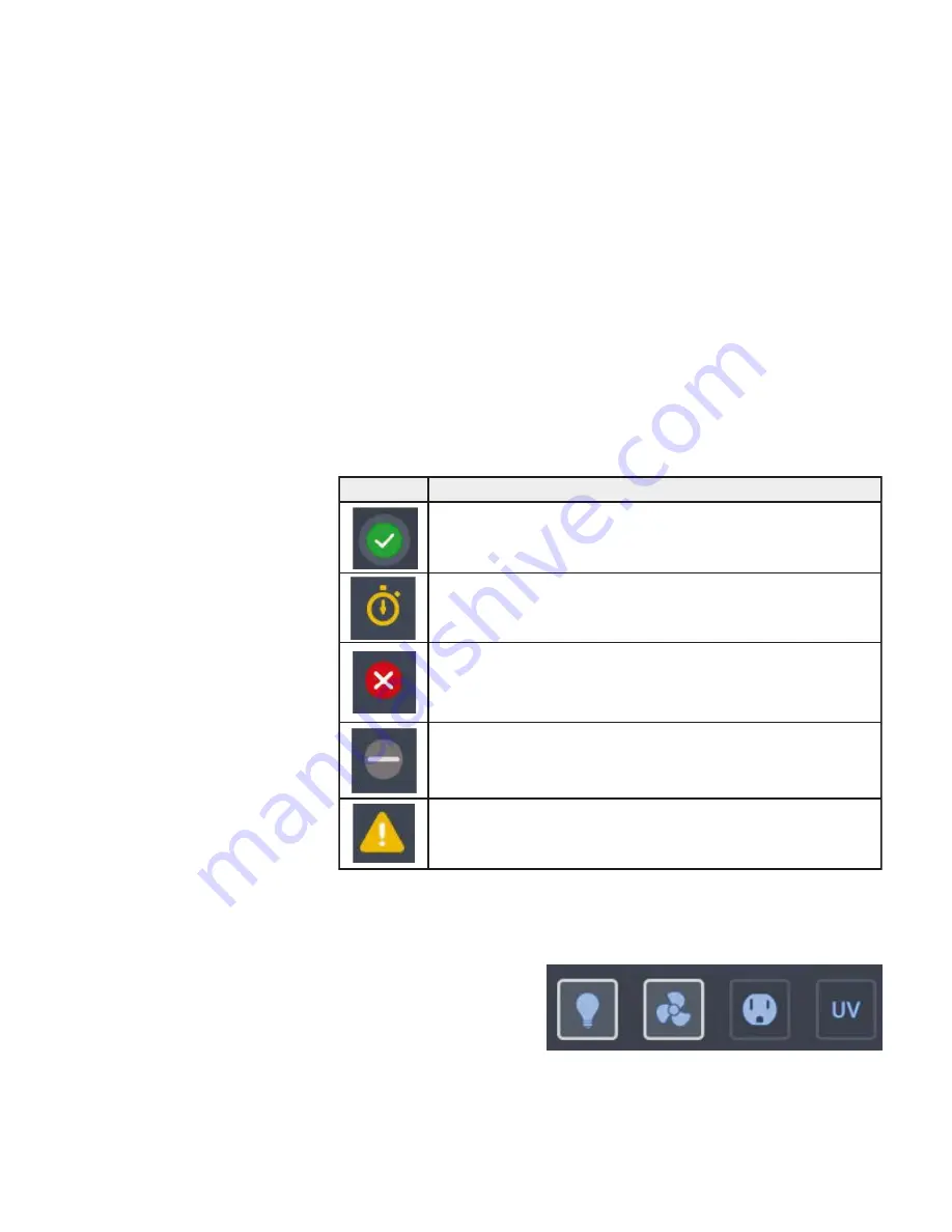
Three status indicator boxes appear in the center of the Main Screen. They
show, from left to right, the state of the window, downflow and inflow
statuses. Status indicator boxes may display with five different status icons:
The Control Panel in Screen Region R2B contains a complete set of
controls for operating the functions of the biological safety cabinet, as can
be seen in Figure 4-9.
The Control Panel is
visible at all times below
the Main Screen.
4-6 Model 1500 Series A2
Thermo Scientific
Section 4
Operation
Indicator
Meaning
The checkmark on the green circle indicates that this particular function is
working properly
The yellow animated “Timer” icon indicates that the unit is working up
towards an operational state.
The white cross on the red circle indicates that there is a problem with that
particular function.
The light gray dash on the gray circle signifies there is no activity. This icon
indicates, for example, that there is no airflow when the unit is on, but the
blowers are off.
The yellow alert triangle icon indicates that there is an alert with that particu-
lar function.
Main Screen (Region R2)
(continued)
Control Panel (Region
R2B)
Figure 4-9.
Control Panel for fully equipped Unit


