CSR-20 & CSR-40, September 1999
Structural/Accessory Maintenance
Partlow (Model SR) Recording Thermometer
7-3
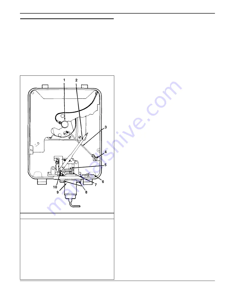
Partlow (Model SR) Recording Thermometer
(Option)
The 31-day Partlow Recorder is mechanically driven by a
spring wound mechanism. The sensor bulb is mounted in the
evaporator to record the return air temperature.
The recording thermometer should be inspected and
cleaned to ensure that the stylus produces smooth clean lines
and records accurate temperature readings. When changing
charts, wipe the stylus and chart platen with a clean, damp
cloth to remove material transferred from the back of the chart
to the platen by the pressure of the stylus.
Recording Chart Replacement
1.
To change the charts, remove the knurled chart nut from
the drive shaft and remove the chart.
2.
Install the new chart on the chart drive shaft. Position the
chart edge under the four clips.
3.
Replace the chant nut loosely and rotate the chart so that
the correct time is indicated by the stylus. In order to
operate the stylus with the door open for the purpose of
checking or zeroing the control, the lifter arm can be
locked in this lowered position by pushing down on the
lifter arm shaft and rotating the arm on its pivot point. If
the lifter arm does not retract away from the stylus when
the door is closed, reposition the arm on the shaft by loos-
ening the Allen screw on the lifter arm.
4.
Hold the recording chart in position and tighten the chart
nut finger tight.
5.
Lower the pen by rotating the lifting arm counterclock-
wise and pushing the pen against the chart. If there is
insufficient pressure on the stylus to mark the chart, care-
fully grip the pivot end of the stylus warm where it is riv-
eted to the stamping with a pair of long-nosed pliers. Bend
the stamping toward the instrument. Care must be used
not to bend the stylus arm, but only the stamping to which
it is attached.
Marking System Calibration
1.
Visually inspect the recording thermometer sensing bulb
located in the evaporator near the return air grille. Make
sure it is securely fastened and clear of debris.
2.
Start the unit and adjust the temperature setpoint to 0 C
(32 F). Operate the unit until the return air temperature
reaches 0 C (32 F). Enter the View menu on the con-
troller display and scroll to the return air temperature
(“RET”) screen. Press the ENTER key to lock the “RET”
screen on the display.
5.
Wait at least 5 minutes to allow the recording thermome-
ter sensing bulb temperature to stabilize. Then compare
the “RET” temperature in the controller display with the
recording stylus of the recorder. Write down both read-
ings.
6.
If the average difference is 0.6 C (1.0 F) or less, DO NOT
attempt to recalibrate.
Partlow (SR) Recording Thermometer
1. Knurled Knob
2. Recording Stylus
3. Lifter Arm
4. Allen Screw
5. Set Screw “S”
6. Key Mounting Clip
7. Adjustment Shaft “J”
8. Element Flange Screws “D”
9. Thermal Element
10. Stamping


