background image

C-9

Themis Computer

C—Red Hat Enterprise Linux 5 Installation

Installation


Click 

Next

.

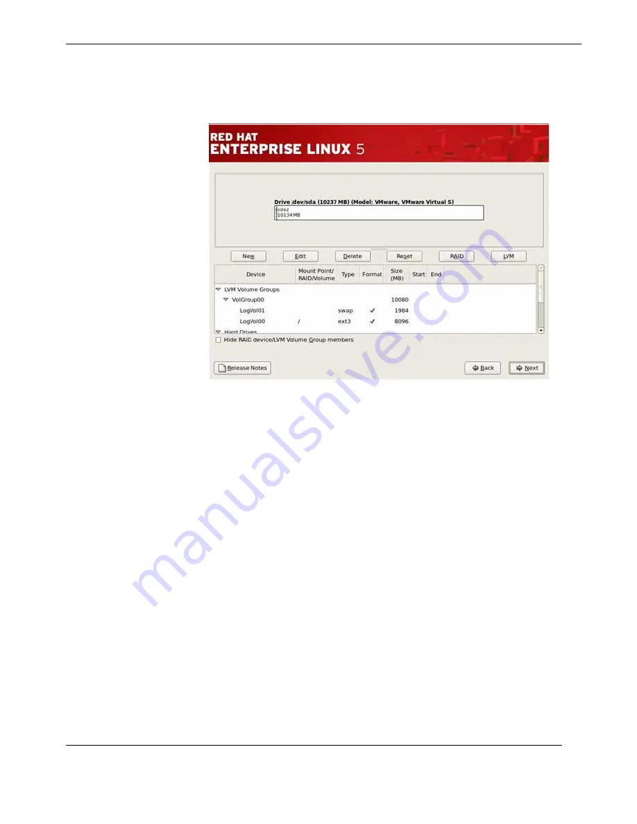
Step 10:

Once you have configured your partitions, set up a boot loader. If you

select “No”, Boot Loader will be Installed, you’ll need to use a third-party boot
loader such as Partition Magic or Microsoft’s TLDR. Unless you want to set up a
Boot Loader Password or Configure Advanced Boot Loader Options (see 

Figure

C-10

 on page C-10).

Figure C-9.  

Creating a Custom Layout

Содержание RES-XR4-3U

Страница 1: ...RES XR4 3U RES XR4 3U Installation Manual Installation Manual 3RU Rack Mount Rugged Enterprise Server with Multiple Motherboard Configurations Xeon CPUs Version 1 3 Par t Number 120918 024...

Страница 2: ...n t e r p r i s e S e r v e r RES XR4 3U RES XR4 3U 3 R U R u g g e d E n t e r p r i s e S e r v e r RES XR4 3U RES XR4 3U 3 R U R u g g e d E n t e r p r i s e S e r v e r RES XR4 3U RES XR4 3U 3 R...

Страница 3: ...77 80 Fax 33 476 14 77 89 Themis Computer Americas and Pacific Rim 47200 Bayside Parkway Fremont CA 94538 Phone 510 252 0870 Fax 510 490 5529 World Wide Web http www themis com RES XR4 3U Installation...

Страница 4: ...uter Inc Intel and Xeon are registered trademarks of Intel Corporation Red Hat is a registered trademark of Red Hat Inc Linux is a registered trademark of Linus Torvalds SuperMicro and SuperDoctor are...

Страница 5: ...d CPU version 2 and DC power supply information and Power Supply Monitoring section in Chapter 1 Corrected LED colors in Figure 1 4 Corrected updated LAN section in Table 1 3 Corrected no fail fan ico...

Страница 6: ...d by a number of other power consumers Do not use an extension cable Only use the mains cable supplied Power cord requirements Europe A power supply unit operating at a nominal voltage of 240V must us...

Страница 7: ...ese cases the device must be shut down and secured against unintentional operation Repairs service may only be carried out by a Themis Computer qualified ser vice technician Do not open the chassis or...

Страница 8: ...perly grounded when touching a sensitive board component or assembly 4 Store electrostatic sensitive boards in protective packaging or on conductive foam Grounding Methods Finnish laite on liitett v s...

Страница 9: ...n 16 AWG 11 Overcurrent Protection relies on proper building installation and Earth connec tion ground 12 High Voltage Earth connection is essential before connecting the power supply units Instructio...

Страница 10: ...st not be dis posed of with your other household waste Instead it is your responsibility to dispose of your waste equipment by handing it to a designated collection point for the recy cling of electri...

Страница 11: ...r ber stolpern k nnen F r den Netzanschluss d rfen keine Verteilerdosen benutzt werden an die noch andere Stromverbraucher angeschlossen sind Verwenden Sie keine Verl ngerungskabel Verwenden Sie nur d...

Страница 12: ...ontaler Lage betrieben werden Die Betriebssicherheit des Ger tes ist nicht mehr gew hrleistet wenn das Ger t sichtbare Besch digungen aufweist oder das Ger t nicht mehr funktioniert In diesen F llen m...

Страница 13: ...Ort in ihrem Beh lter 3 Achten Sie beim Ber hren empfindlicher Platinen Bauteile oder Baugruppen stets auf eine gute Eigenerdung 4 Lagern Sie elektrostatisch empfindliche Platinen in Schutzverpackung...

Страница 14: ...ge 9 Die Gr e der Erdungsleitung sollte nicht weniger als 16 AWG betragen 10 berstromschutz ist auf ordnungsgem e Geb udeinstallation und richtigen Erdungsanschluss Masse angewiesen 11 Hochspannung De...

Страница 15: ...iagram 1 15 1 2 3 X9DBL Block Diagram 1 16 1 3 Chipset Overview 1 17 1 3 1 C602 C606 Chipset 1 17 1 3 2 Main Features of E5 2400 E5 2600 V2 Series Processor and C602 C606 Chipset 1 18 1 4 Special Feat...

Страница 16: ...ssory Kit 1 30 1 6 2 Rack Mount Slides Optional 1 31 1 6 3 Approximate System Weights 1 31 2 Installation and Operation 2 1 2 1 Installation Procedures 2 1 2 1 1 Remove Protective Top Cover 2 1 2 1 2...

Страница 17: ...ity 3 1 3 1 2 How To Change the Configuration Data 3 2 3 1 3 Starting the Setup Utility 3 2 3 2 Main Setup 3 3 3 2 1 System Overview 3 4 3 2 1 1 System Time System Date 3 4 3 2 1 2 Supermicro Motherbo...

Страница 18: ...Maximum Read Request 3 21 3 3 7 8 ASPM Support 3 21 3 3 7 9 CPU1 Slot 1 PCI E 3 0 x8 OPROM CPU1 Slot 2 PCI E 3 0 x8 OPROM CPU1 Slot 3 PCI E 3 0 x8 OPROM CPU2 Slot 4 PCI E 3 0 x16 OPROM CPU2 Slot 5 PC...

Страница 19: ...ions 3 30 3 4 1 2 Erasing Settings 3 31 3 5 IPMI 3 33 3 5 1 System Event Log SEL 3 33 3 5 1 1 Enabling Disabling Options 3 33 3 5 1 2 Erasing Settings 3 34 3 5 1 3 Custom EFI Logging Options 3 34 3 5...

Страница 20: ...orts A 4 A 6 IPMI Dedicated LAN Port A 4 Appendix B Rack Mount Slide Installation B 1 Appendix C Red Hat Enterprise Linux 5 Installation C 1 C 1 Introduction C 1 C 2 Installation C 1 Appendix D Option...

Страница 21: ...X9DRH Block Diagram 1 14 Figure 1 10 X9DR3 Block Diagram 1 15 Figure 1 11 X9DBL Block Diagram 1 16 Figure 1 12 RES XR4 3U with Noise Baffle Installed Front View 1 27 Figure 1 13 RES XR4 3U with Rear...

Страница 22: ...R4 3U Power Supply Locking Mechanism 2 22 Figure 2 21 Right Rack Mount Bracket 2 24 Figure 2 22 AC Power Socket and LED on the RES XR4 3U Rear 2 25 Figure 2 23 System Power Button and LED on the RES X...

Страница 23: ...gure C 11 Master Boot Record MBR C 11 Figure C 12 Network Devices List C 12 Figure C 13 Edit Interface Pop Up Screen C 13 Figure C 14 Selecting Time Zone C 14 Figure C 15 Setting Up Root Account and P...

Страница 24: ...ble 1 8 Approximate Weights of the RES XR4 Series 1 31 Table 2 1 RES XR4 3U System Memory Capacity 2 3 Table 2 2 X9DRH and X9DR3 Slot CPU Assignment 2 4 Table 2 3 X9DBL Slot CPU Assignment 2 4 Table 2...

Страница 25: ...xxiii Themis Computer Table of Contents Table D 2 COM1 Serial Connector Pinout Signal Descriptions J8 and J9 D 5 Table D 3 Stereo Audio Out Connector Pinout Signal Descriptions J1 D 6...

Страница 26: ...xxiv Themis Computer RES XR4 3U Installation Manual Version 1 3...

Страница 27: ...t the Themis Rugged Enterprise Server RES XR4 3U see Figure 1 below RES XR4 3U supports the SuperMicro X9DRH and X9DR3 motherboards in either a 17 deep front I O chassis or a 20 deep rear I O chassis...

Страница 28: ...military aerospace and telecommunica tions industries An overview of RES XR4 3U design and specifications is given in Chapter 1 Overview and Specifications of this manual This manual is intended for a...

Страница 29: ...This may involve but is not restricted to heavy equipment or sharp objects To reduce the risk follow the instructions accompanying this symbol Warning A warning describes a procedure or action that ma...

Страница 30: ...RES XR4 3U Installation Manual Version 1 3 xxviii Themis Computer...

Страница 31: ...upports two Intel Xeon processors each with a QPI Quick Path Interconnect up to 8 0 GT s Giga Transfers per second supporting memory capacities as listed in Table 1 2 Its computer graphics intensive a...

Страница 32: ...and X9DR3 Intel C606 602 PCH Memory X9DRH and X9DR3 Sixteen 16 240 pin DIMMs supporting up to 1TB of DDR3 1866 1600 1333 1066 800 MHz SDRAM X9DBL Six 6 240 pin DIMMs supporting up to 384GB of DDR3 160...

Страница 33: ...specified at the time the system is purchased Also included on the front panel is a system power ON OFF button and LEDs The I O panel contains I O faceplates for seven PCI cards two AC power supplies...

Страница 34: ...C Power Socket 3 prong NEMA 15 Dual Power Supplies System Power Power Supply Latch Lock ON OFF Switch CD RW DVD ROM Combo Slimline Drive Rear I O Panel see Figure 1 5 page 1 7 17 43 4 cm 19 with Rack...

Страница 35: ...are described in Table 1 4 on page 1 8 Figure 1 3 External Features of RES XR4 3U Front I O Front View Doors Removed AC Power Socket 3 prong NEMA 15 Dual Power Supplies System Power Power Supply Latch...

Страница 36: ...3 1 6 Themis Computer Figure 1 4 RES XR4 3U System LEDs and Indicators LEDs NIC1 NIC2 Storage Drives Power Power Fail PS1 Overheat Fan Fail Power Fail PS2 C ENET2 ENET1 Rear I O Chassis Front Panel D...

Страница 37: ...Warns that the system is exceeding specified temperature parameters The CPU overheat warning function must be enabled in the BIOS thus allowing the user to define an overheat temperature which when e...

Страница 38: ...AC power Or On red LED Power Fail LED Left or Right Power Supply a Note system is powered off AC power has been inter rupted to both power sup ply modules When power is restored but system is still of...

Страница 39: ...igure 1 5 I O Panel Diagrams X9DBL I O Connectors PS 2 Keyboard COM 1 Port PS 2 Mouse IPMI Dedicated LAN VGA Port LAN 2 Port LAN 1 Port USB1 top USB0 bottom Gigabit Ethernet X9DRH I O Connectors X9DR3...

Страница 40: ...oard COM 1 Serial Port One DB9 male connector on rear panel to attach a serial device to COM 1 port Note A second serial port COM 2 can be accessed directly from the motherboard VGA Port 15 pin VGA co...

Страница 41: ...ecifications 1 1 4 Internal Views Figure 1 6 RES XR4 3U Open Top View X9DRH Motherboard Power Supplies CPU 2 and adjacent memory slots CPU 1 and adjacent memory slots PCIe Slots 120 mm Fans CD DVD Com...

Страница 42: ...ation Manual Version 1 3 Figure 1 7 RES XR4 3U Open Top View X9DBL Motherboard Power Supplies CPU 1 an adjacent memory s PCIe Slots 120 mm Fans Lithium Battery CD DVD Combo Drive Housing Storage Drive...

Страница 43: ...ns Overview Figure 1 8 RES XR4 3U Open Top View X9DR3 Motherboard Power Supplies CPU 2 and adjacent memory slots CPU 1 and adjacent memory slots PCIe Slots 120 mm Fans CD DVD Combo Drive Housing Stora...

Страница 44: ...X8 PCI E X8 G3 PCI C 1 C 2 PCI E X8 G3 SAS2 8 SNB CORE DDR III E5 2600 8 SNB CORE DDR III QPI 8G 4GB s SAS SAS P1 P1 P0 SLOT 3 SLOT 1 SLOT 2 SLOT 5 SLOT 6 SLOT 7 SLOT 4 PCI E X8 PCI E X8 PCI E X8 G3 P...

Страница 45: ...der SLOT 3 PCI E X8 USB 2 0 3 0 Gb S PCH C606 C602 PCI E X16 G3 DMI2 LANE5 LANE1 2 3 4 SPI P0 USB SATA 2 Rear 4 Front 1 Type A BMC PCI E X8 G3 PCI 32 P1 C1 P1 C2 PCI E X8 G3 SCU 8 SNB CORE DDR3 QPI 8G...

Страница 46: ...Gen2 3 0 Gb S for Ports 2 5 SCU SATA SAS PCI E 1 PCI E 1 6 0 Gb S PEG0 PCI E x4 CPU 2 DDR 3 P1 3 3 1 CPU 1 DDR 3 P0 1 3 1 DMI D 1 800 1066 1333 1600 DDR3 E 1 F 1 PCI E X1 Gen2 A 1 800 1066 1333 1600 D...

Страница 47: ...06 chipset With the Intel QuickPath Interconnect QPI controller built in the processor the C602 C606 Series Processor platform offers point to point serial interconnect inter face with CPU to CPU tran...

Страница 48: ...tel SpeedStep Technology Two full width Intel QuickPath interconnect link s up to 8 0 GT s of data trans fer rate in each direction Virtualization Technology Integrated Management Engine supported Poi...

Страница 49: ...ning is given or an error message is sent to the screen Users can adjust the voltage thresholds to define the sensitivity of the voltage monitor 1 4 2 1 Fan Status Monitor The RES XR4 3U has two 120 m...

Страница 50: ...C bus used for system monitoring This bus can be reached through the Baseboard Management Controller BMC described in subsequent paragraphs on the moth erboard Sample Linux commands to do this are inc...

Страница 51: ...the system This includes the hardware the operating sys tem and the application software As a result the system can automatically turn peripherals CD ROMs NICs storage drives and printers for example...

Страница 52: ...the PCI interface Virtual media and keyboard Video Mouse Redirection KVMR With blade ori ented Super I O capability built in the WPCM450R Controller is ideal for remote system management The WPCM450R...

Страница 53: ...d Digital outputs SPI Flash Host BIOS and firmware bootstrap program supported Reduced Media Independent Interface RMII OS Operating System Independent IPMI Hardware Health Monitoring Remote access co...

Страница 54: ...to chassis Left and right rack mount slides are optional 19 Rack Mountable with Slide capability Left and right rack mount tabs attached to chassis Left and right rack mount slides are optional Temper...

Страница 55: ...ccupies both power supply bays In this case there is no redundancy in the power supply subsystem Power sup ply options should be specified at the time of your order Table 1 7 RES XR4 3U Electrical Spe...

Страница 56: ...ing the system to survive a maximum 3 axis shock load of 30 g at 25 ms duration 1 5 2 2 Electrostatic Discharge The RES XR4 3U is designed to tolerate electrostatic pulses up to 15 kilovolts KV with n...

Страница 57: ...do this loosen the two 2 captive knurled Phillips screws holding the baffle to the chassis see A Figure 1 12 and remove the baffle Figure 1 12 RES XR4 3U with Noise Baffle Installed Front View Front...

Страница 58: ...baffle door To do this loosen the four 4 captive knurled Phillips screws A in Figure 1 13 holding the baffle door to the chassis and swing the door downward away from the chassis exposing the rear co...

Страница 59: ...th the baffle door closed To do this five 5 M3x4 flathead Phillips screws B in Figure 1 13 page 1 28 must be removed two on each side of the baffle and one captive in the middle on the top After remov...

Страница 60: ...cessory Kit Each RES XR4 3U is packaged with an Accessory Kit consisting of the following items A Two AC Power Cords B Two Storage Drive Barrel Keys C All applicable paperwork When you unpack the RES...

Страница 61: ...ription RES XR4 1U 19 5 lbs 8 9 kg 2 20 Includes All CPU sockets filled 6 DIMMs 2 storage drives 2 PCI cards 1 CD RW DVD ROM drive 2 power supplies 17 lbs 7 7 kg 2 17 RES XR4 2U 25 lbs 11 4 kg 2 20 In...

Страница 62: ...All DIMM slots filled Two PCI E Storage Canisters Four PCI E flash based storage cards Total of eight PCI E storage cards per system RES NT2 1U 23 72 lbs 10 76 2 24 Includes All CPU sockets filled 8...

Страница 63: ...directly to page 2 14 page 2 18 or page 2 21 respectively Replacement of motherboard components requires removal of the protective cover 2 1 1 Remove Protective Top Cover To access a motherboard comp...

Страница 64: ...slots on the chassis top edges see B Figure 2 1 Remove the cover by sliding it toward the rear until it is free of these chassis slots 3 Store the cover in a safe place until it is replaced Figure 2 1...

Страница 65: ...system Table 2 1 RES XR4 3U System Memory Capacity Motherboard Memory Parameters DDR3 DIMM Capacity DDR3 Registered ECC Speed MHz Number of DIMMS Pins per DIMM X9DRH up to 1TB ECC LRDIMM 512GB ECC RD...

Страница 66: ...es below DIMMs should be installed in pairs for best performance Ensure that the minimum memory requirements have been met for you particu lar OS Operating System Table 2 2 X9DRH and X9DR3 Slot CPU As...

Страница 67: ...2 CPUs 10 16 DIMMs CPU1 CPU2 P1 DIMMA1 P1 DIMMB1 P1 DIMMC1 P1 DIMMD1 P2 DIMME1 P2 DIMMF1 P2 DIMMG1 P2 DIMMH1 Any memory pairs in P1 P2 DIMM slots 2 CPUs 16 DIMMs CPU1 CPU2 P1 DIMMA1 P1 DIMMB1 P1 DIMMC...

Страница 68: ...or in the fol lowing manner see Figure 2 2 Screw A After removing Screw A remove the PCI card retainer bracket and store in a safe place Screw B The screw marked B in Figure 2 2 is recessed Remove it...

Страница 69: ...t can be removed from the system After the air flow diverter has been removed the memory module slots will be exposed see Figure 2 3 Figure 2 3 X9DRH X9DR3 Memory Module Slot Locations P2 DIMM E1 P2 D...

Страница 70: ...remove it by gently pressing down and outward on the latches at both ends of the slot see Figure 2 5 on page 2 9 then pulling the old module directly up from the slot until it is free of the connecto...

Страница 71: ...e system replace the air flow diverter and secure it with the six screws previously removed 5 Replace the PCI card retainer bracket and secure it with the single screw removed in Step 1 on page 2 6 6...

Страница 72: ...See Table 2 6 All slots support cards up to 12 28 inches long Table 2 6 RES XR4 3U PCI e 3 0 Slots Motherboard PCI e 3 0 Slotsa a Both CPUs must be installed to access all PCIe slots 33MHz x16 x8 X9DR...

Страница 73: ...nd Operation Installation Procedures 2 11 Themis Computer Figure 2 7 X9DR3 PCI Slots Slot 2 3 4 5 6 1 X16 X16 X16 X8 X8 X8 Figure 2 8 X9DBL PCI Slots X16 X8 X8 X8 X4 in X8 Slot Slot 2 3 4 5 6 1 PCI 32...

Страница 74: ...hassis opening 5 Repeat Step 3 and Step 4 until all additional cards have been installed 6 Swing the PCI card clamp back to its position over the PCI card I O panels and tighten the captive knurled sc...

Страница 75: ...Battery Perform the following steps to remove the lithium battery 1 Make sure the system is powered off see Operation on page 2 25 2 If you cannot access the lithium battery directly move and or deta...

Страница 76: ...w lithium battery 1 Tilt the replacement battery into the empty socket so that it is angled under the battery latch see B Figure 2 11 2 Carefully press down on the battery until it clicks firmly into...

Страница 77: ...way from the chassis The accessory kit shipped with your RES XR4 3U contains two barrel lock keys This provides you the option of unlocking locking the storage drives see Figure 2 13 on page 2 16 Figu...

Страница 78: ...ive 5 Grab the latch handle and pull the drive completely away from its slot Figure 2 13 Unlocking the RES XR4 3U Storage Drives Front Doors Removed Drive Lock one per drive Drive Release Button Drive...

Страница 79: ...A push the latch lock B Latch Lock Latch Handle and pull drive out with the latch handle C 45 degrees clockwise Barrel Key Remove the four screws securing D Place the four screws in a plastic E Drive...

Страница 80: ...torage drive repeat Steps 1 4 for each additional drive 2 1 6 Removable 120 mm Fan The RES XR4 3U contains two high speed 120 mm fans Both fans are removable for replacement in case of a fan failure C...

Страница 81: ...pward exposing the three 120 mm fans 2 Each fan is secured by a locking latch on the left hand side To remove a fan press the latch lock toward the center of the fan with the left hand index finger Wi...

Страница 82: ...eted close the fan lid while holding the fan lid lock in the open position to the left see Figure 2 16 on page 2 19 until the lid is firmly seated and flush with the top of the chassis While apply ing...

Страница 83: ...ring N 1 redundant power supply can be hot swapped while the sys tem is still on and operational 2 2 1 DC Power Supply Option The optional DC power supplies are available in 28VDC and 48VDC They have...

Страница 84: ...handle and the right thumb on the left side of the power supply locking lever Figure 2 20 The RES XR4 3U Power Supply Locking Mechanism Extraction Push right to release power supply Handle Power Suppl...

Страница 85: ...he extraction handle facing to the right and the power LED at the top see Figure 2 20 on page 2 22 2 Push the power supply carefully into its slot until it is firmly seated a click will be heard when...

Страница 86: ...n 2 3 2 Rack Mount Slides Optional Rack Mount Slides can be mounted on each side of the RES XR4 3U for the pur pose of sliding the unit in and out of a rack Mounting slides are optional and should be...

Страница 87: ...2 Turning the System On 1 Plug the AC power cord from each of the RES XR4 3U power supplies into a live AC outlet 2 On the front of the RES XR4 3U push the system power on off button see Figure 2 23 T...

Страница 88: ...tallation The subject of installing the Linux operating system onto the RES XR4 3U is detailed in Appendix C Red Hat Enterprise Linux 5 Installation 2 4 4 Turning the System Off 1 To turn the RES XR4...

Страница 89: ...BIOS Setup Utility To enter the AMI BIOS Setup Utility screens press the Delete key while the sys tem is booting up Each main BIOS menu option is described in this manual The Main BIOS setup menu scr...

Страница 90: ...AMI BIOS Setup utility This Setup utility can be accessed by pressing Del at the appropriate time during system boot 3 1 3 Starting the Setup Utility Normally the only visible Power On Self Test POST...

Страница 91: ...reen is shown below Caution Do not upgrade the BIOS unless your system has a BIOS related issue Flashing the wrong BIOS can cause irreparable damage to the system In no event shall Supermicro be liabl...

Страница 92: ...be entered in Day MM DD YY format The time is entered in HH MM SS format 3 2 1 2 Supermicro Motherboard Data SMC MB Model number s This item displays the SuperMicro motherboard model installed SMC Ver...

Страница 93: ...to be modified between POST mes sages or the OEM logo Select Disabled to display the POST messages Select Enabled to display the OEM logo instead of the normal POST messages The options are Enabled d...

Страница 94: ...item is set to Disabled the ROM BIOS of the host adaptors will not capture Interrupt 19 and the drives attached to these adaptors will not func tion as bootable devices The options are Enabled defaul...

Страница 95: ...te default 3 3 3 CPU Configurations This submenu displays the information of the CPU as detected by the BIOS It also allows the user to configure CPU settings 3 3 3 1 Socket 1 Socket 2 CPU Information...

Страница 96: ...nabled and Disabled Active Processor Cores Set to Enabled to use a processor s second core and above Please refer to Intel s website for more information The options are All 1 and 2 Limit CPUID Maximu...

Страница 97: ...ization Technology Available when supported by the CPU Select Enabled to support Intel Virtualization Technology which will allow one plat form to run multiple operating systems and applications in in...

Страница 98: ...ltage and fre quency This makes the processor more energy efficient resulting in further gains The options are HW ALL SW ALL and SW ANY CPU C3 Report Available when Power Technology is set to Custom S...

Страница 99: ...alanced Energy and Energy Efficient Factory Long Duration Power Limit This item displays the power limit in watts set by the manufacturer during which long duration power is maintained Long Duration P...

Страница 100: ...echnology significantly reduces CPU over head by leveraging CPU architectural improvements freeing the system resource for other tasks The options are Disabled and Enabled DCA Support Select Enabled t...

Страница 101: ...for Port 2A Select GEN2 to enable PCI Exp Generation 2 support for Port 2A Select GEN3 to enable PCI Exp Generation 3 support for Port 2A The options are GEN1 GEN2 and GEN3 IOU3 PCIe Port This featur...

Страница 102: ...eed between IOU2 and PCIe port The default setting is x8x8 Slot 2 Link Speed Select GEN1 to enable PCI Exp Generation 1 support for Slot 2 Port Select GEN2 to enable PCI Exp Generation 2 support for S...

Страница 103: ...t This feature determines how to distribute the available PCI Express lanes to the PCI E Root Ports QPI Quick Path Interconnect Configuration Current QPI Link Speed This item displays the current stat...

Страница 104: ...al copies of all data in memory for data backup When Lockstep is selected the motherboard uses two areas of memory to run the same set of operations in parallel The options are Independent Mirroring L...

Страница 105: ...U to correct correctable mem ory errors found on a memory module When the CPU or I O issues a demand read command and the read data from memory turns out to be a correctable error the error is correct...

Страница 106: ...t Disabled Select Enabled to support legacy USB devices Select Auto to disable legacy support if USB devices are not present Select Disabled to have USB devices available for EFI Extensive Firmware In...

Страница 107: ...SATA Controller 1 is Enhanced AHCI Mode The following items are displayed when the AHCI Mode is selected Aggressive Link Power Management When Enabled the SATA AHCI controller manages the power usage...

Страница 108: ...a a storage device if a SAS device is installed The options are Disabled and Enabled 3 3 6 3 SCU Port 0 3 The SCU devices detected by the BIOS will be displayed 3 3 7 PCIe PCI PnP Configuration This s...

Страница 109: ...or Event The options are Enabled and Disabled 3 3 7 6 Maximum Payload This feature selects the setting for the PCIE maximum payload size The options are Auto 128 Bytes 256 Bytes 512 Bytes 1024 Bytes 2...

Страница 110: ...1 Option ROM Load Onboard LAN2 Option ROM Select Enabled to enable the onboard LAN1 Option ROM LAN2 Option ROM This is to boot the computer using a network device The default setting for LAN1 Option R...

Страница 111: ...from accessing any system resources When this option is set to Disabled the serial port becomes unavailable The options are Auto IO 3F8h IRQ 4 IO 3F8h IRQ 3 4 5 6 7 10 11 12 IO 2F8h IRQ 3 4 5 6 7 10...

Страница 112: ...t 0 or COM Port 1 as specified by the user COM 1 COM 2 These two submenus allow the user to configure the following Console Redirection settings for a COM Port specified by the user Console Redirectio...

Страница 113: ...s sion Select Mark to add mark as a parity bit to be sent along with the data bits Select Space to add a Space as a parity bit to be sent with your data bits The options are None Even Odd Mark and Spa...

Страница 114: ...onsole Redirection for EMS Select Enabled to use a COM Port selected by the user for Console Redirection The options are Enabled and Disabled Console Redirection Settings for EMS This feature allows t...

Страница 115: ...Advanced Configuration and Power Interface ACPI power management settings for your system 3 3 9 1 ACPI Sleep State Use this feature to select the ACPI State when the system is in sleep mode Select S1...

Страница 116: ...0 3 Pending Operation Use this item to schedule an operation for the security device The options are None Enable Take Ownership Disable Take Ownership and TPM Clear 3 3 10 4 Current Status Information...

Страница 117: ...his feature displays the features that need to be enabled for the Intel Trusted Exe cution Technology to work properly in the system VT d Support Intel Virtualization Technology with Direct I O suppor...

Страница 118: ...Settings 3 4 1 1 Enabling Disabling Options Smbios Event Log Change this item to enable or disable all features of the Smbios Event Logging dur ing boot The options are Enabled and Disabled Runtime Er...

Страница 119: ...ent logs that exceed the limit when the SMBIOS event log is full Select Do Nothing for the sys tem to do nothing when the SMBIOS event log is full The options are Do Nothing and Erase Immediately Log...

Страница 120: ...ew Smbios Event Log This feature displays the contents of the SmBIOS Event Log This item allows the user to view the event in the SMBIOS event log Select this item and press Enter to view the status o...

Страница 121: ...nterface IPMI set tings IPMI Firmware Revision This item indicates the IPMI firmware revision used in your system IPMI Status This item indicates the status of the IPMI firmware installed in your syst...

Страница 122: ...event log is full The options are Do Nothing and Erase Immediately 3 5 1 3 Custom EFI Logging Options Log EFI Status Codes Select Enabled to log EFI Extensible Firmware Interface Status Codes Error C...

Страница 123: ...he value of each three digit number separated by dots should not exceed 255 Station MAC Address This item displays the Station Mac address for this computer Mac addresses are 6 two digit hexadecimal n...

Страница 124: ...Boot Option 1 Boot Option 2 Boot Option 3 Use this feature to specify the sequence of boot device priority Network Device BBS Priorities This option sets the order of the legacy network devices detect...

Страница 125: ...e this feature to set the Administrator Password which is required to enter the BIOS setup utility The length of the password should be from 3 characters to 20 characters long 3 7 2 User Password Use...

Страница 126: ...e system configuration and reboot the computer Select Discard Changes and Exit and press Enter When the dialog box appears asking you if you want to exit the BIOS setup without saving select Yes to qu...

Страница 127: ...es select Yes to load the values previous saved or select No to keep the changes you ve made so far 3 8 3 3 Restore Defaults Select this feature and press Enter to load the default settings that help...

Страница 128: ...ontinue with bootup procedure If a fatal error occurs you should consult with your system manufacturer for possible repairs These fatal errors are usually communicated through a series of audible beep...

Страница 129: ...the recovery process to load the file A USB flash device such as a USB Flash Drive a USB CDROM or a USB CDRW device can be used for this purpose 1 Insert the USB device that contains the new BIOS imag...

Страница 130: ...the user to use a serial port to load a BIOS image for Boot Sector recovery This feature is usually used for embedded systems that rely on a serial port for remote access and debugging Requirements In...

Страница 131: ...the instructions given on the screen to update the BIOS These instructions are also shown below a At the prompt press the SpaceBar to update the BIOS b When asked to confirm BIOS updating press y to...

Страница 132: ...1 3 a Select the Transfer menu and enter Send see Figure 3 8 b Specify the location of the ROM file and select the proper protocol XMo dem c Press Send to start ROM File extraction see Figure 3 9 Figu...

Страница 133: ...flash is completed the system will reboot Figure 3 10 FLASH Recovery Note AMBIOS Serial Flash will work with any terminal communications pro gram that supports VT 100 and XModem protocols including pr...

Страница 134: ...3 46 Themis Computer RES XR4 3U Installation Manual Version 1 3...

Страница 135: ...oard and Mouse The RES XR4 3U provides a 6 pin female mini DIN connector for the PS 2 key board and another for the PS 2 mouse Signals for both connectors are defined in Table A 1 Table A 1 PS 2 Keybo...

Страница 136: ...XR4 3U supports one male DB9 serial port connector on the rear I O panel see Figure A 2 TTYA COM1 COM1 pinout signal descriptions are listed in Table A 3 Figure A 1 USB Connector Pinout Table A 2 USB...

Страница 137: ...Port 1 5 6 10 11 15 Table A 4 RES XR4 3U VGA Connector Pin Signals Pin VGA Signal Description Pin VGA Signal Description 1 RED OUT Red signal output 9 VCC Filtered Vcc voltage source 2 GREEN OUT Green...

Страница 138: ...hernet LAN port on the RES XR4 3U rear I O panel has identical pinout and signal descriptions as the LAN Ethernet ports described in Section A 5 Gigabit Ethernet LAN Ports Figure A 4 Ethernet Connecto...

Страница 139: ...n each side to accommodate 8 32 size screws included with the rack mount slide kit steel slides require four mount ing holes and aluminum slides require three mounting holes see Figure B 1 Figure B 1...

Страница 140: ...the depth of the equipment rack adjust and attach the front and rear slide brackets to the outside slide section using the screws washers and nuts provided with the slide kit 4 With all slide brackets...

Страница 141: ...tside slide section with screws Outside slide section washers and nuts included in slide kit Attach the rear long slide bracket to the outside slide section with screws washers and nuts included in sl...

Страница 142: ...Themis Computer RES XR4 3U Installation Manual Version 1 3 B 4...

Страница 143: ...during the installation of Red Hat Enterprise Linux via DVD device From fundamental concepts such as installation preparation to the step by step installation procedure C 2 Installation Step 1 Insert...

Страница 144: ...al Version 1 3 C 2 Themis Computer Step 2 Press the tab key to move focus to the Skip key then press Enter key to Continue see Figure C 2 on page C 2 Figure C 1 Power On after Linux DVD is Inserted in...

Страница 145: ...Figure C 3 on page C 3 Click on the Next button to continue Step 4 Using your mouse select a language to use for the installation The lan guage you select here will become the default language for the...

Страница 146: ...ect the appropriate language click Next to continue Step 5 Using your mouse select the correct layout type for example U S English for the keyboard you would prefer to use for the installation and as...

Страница 147: ...xt to continue Step 6 Enter the installation number if you don t have an installation number select the Skip Entering Installation Number Radio Button Click OK and if you did not enter an installation...

Страница 148: ...using the Create custom layout option of Disk Druid The first three options allow you to perform an automated installation without hav ing to partition your drive s yourself If you do not feel comfor...

Страница 149: ...es and create default layout select this option to remove only Linux partitions partitions created from a previous Linux installation This does not remove other partitions you may have on your hard dr...

Страница 150: ...ve made your selections to proceed Step 9 If you chose one of the automatic partitioning options and selected Review you can either accept the current partition settings click Next or modify the setup...

Страница 151: ...partitions set up a boot loader If you select No Boot Loader will be Installed you ll need to use a third party boot loader such as Partition Magic or Microsoft s TLDR Unless you want to set up a Boot...

Страница 152: ...two places The master boot record MBR This is the recommended place to install a boot loader unless the MBR already starts another operating system loader such as System Commander The MBR is a special...

Страница 153: ...ystem only uses Red Hat Enterprise Linux you should choose the MBR Click the Change Drive Order button if you would like to rearrange the drive order or if your BIOS does not return the correct drive...

Страница 154: ...Netmask for IPv4 Prefix for IPv6 of the device via DHCP or manually if DHCP is not selected and you can choose to activate the device at boot time If you select Acti vate on boot your network interfac...

Страница 155: ...the world see Figure C 14 on page C 14 From here there are two ways for you to select your time zone 1 Using your mouse click on the interactive map to select a specific city rep resented by a yellow...

Страница 156: ...portant steps during your installation Your root account is similar to the administrator account used on Windows NT machines The root account is used to install packages upgrade RPMs and perform most...

Страница 157: ...t for your Red Hat Enterprise Linux installation This screen varies depending on the version of Red Hat Enterprise Linux you are installing see Figure C 16 on page C 16 To customize your package set f...

Страница 158: ...stall Once a package group has been selected if optional components are available you can click on Optional packages to view which packages are installed by default and to add or remove optional packa...

Страница 159: ...Next Step 18 Once you have selected the package groups of your choice you get one last chance to go back before starting the installation process Click Next if you re happy with your choices or click...

Страница 160: ...RES XR4 3U Installation Manual Version 1 3 C 18 Themis Computer Click Next Step 19 Installation Starts see Figure C 19 Figure C 18 Option to Review or Continue Figure C 19 Installation Begins...

Страница 161: ...up sequence has completed the graphical boot loader prompt appears at which you can do any of the following things Press Enter causes the default boot entry to be booted Select a boot label followed b...

Страница 162: ...ntually a login prompt or a GUI login screen if you installed the X Window System and chose to start X automatically appears see Figure C 21 Step 22 Once logged in you are ready to use the desktop see...

Страница 163: ...al port capabilities to the front of any RES system can easily order an optional RES Audio USB Serial Port Custom Module see Figure D 1 that is installed at the Themis factory into an available stor a...

Страница 164: ...gh the Module may be installed into any RES system Figure D 3 on page D 3 shows the internal connections that are made between the RES Custom Module and the RES motherboard Caution Because connections...

Страница 165: ...igure D 3 Attach the Appropriate I O Cables DB9 Serial Port Attach the appropriate I O Cables from the USB Ports A and B Port A Port B Stereo Audio Out Jack Optional RES Custom Module J8 J2 J10 To RES...

Страница 166: ...t Custom Module supports two USB Universal Serial Bus port connectors see Figure D 4 for pinouts USB A and USB B on the front I O panel USB pinout descriptions are listed in Figure D 4 pinout signal d...

Страница 167: ...e D 5 pinout signal descriptions are described in Table D 2 which also shows the serial header J8 connections to serial port J9 Figure D 5 COM1 Serial Connector Pinout J9 Serial Port COM1 J8 1 2 3 4 5...

Страница 168: ...io Connector Pinout J3 Stereo Audio Out Jack J2 Line Out Header J1 1 3 5 7 9 J4 1 2 3 4 Line In Header USB to Audio Chip Header 5 1 2 4 3 No Connection Left Line Out Right Line Out Line In Left Line I...

Страница 169: ...ust be made to the RES chassis in order to support the RES Audio USB Serial Port Custom Module the Custom Module must be spec ified on the purchase order for your RES system Please contact Themis for...

Страница 170: ...D 8 Themis Computer RES XR4 3U Installation Manual Version 1 3...

Страница 171: ...om damage in transit If it becomes necessary to ship in packaging other than that provided by Themis equipment should be wrapped in a moisture resistant covering and placed either in double boxes or i...

Страница 172: ...Figure E 1 page E 2 They comprise a packaging box bottom crush resistant layer and top crush resistant layer The bottom and top crush resistant lay ers are identical components placed so that the side...

Страница 173: ...he bottom of the box Place the equipment on top of the bottom layer right side up Place the other crush resistant layer membrane side down open side up on top of the equipment Press down on the top la...

Страница 174: ...E 4 Themis Computer RES XR4 3U Installation Manual Version 1 3...

Страница 175: ...D 4 B BIOS Setup Utility Advanced Setup Configurations 3 5 ACPI Settings 3 27 ACPI Sleep State 3 27 High Precision Timer 3 27 BOOT Features 3 5 AddOn ROM Display Mode 3 5 Bootup Num Lock 3 6 Interrupt...

Страница 176: ...it 3 11 Power Technology 3 9 C1E Support 3 10 CPU C3 Report 3 10 CPU C6 Report 3 10 CPU C7 Report 3 10 EIST 3 9 Package C State limit 3 11 P STATE Coordination 3 10 Turbo Mode 3 10 Recommended Short D...

Страница 177: ...24 Console Redirection 3 24 Console Redirection for EMS 3 26 Console Redirection Settings 3 24 Trusted Computing 3 28 Current Status Information 3 28 TPM Active Status 3 28 TPM Enable Status 3 28 TPM...

Страница 178: ...autions xxvi Chipset Overview 1 17 C602 C606 Chipset 1 17 Main Features of the E5 2400 E5 2600 Se ries Processor and C602 C606 Chipset 1 18 COM1 serial port 1 10 Comments xxvi Configuration system 2 2...

Страница 179: ...C 10 Setting Up Root Account and Password C 15 Skip Key C 2 Welcome Screen C 3 Linux Installation Guide C 1 Lithium Backup Battery 2 13 lithium battery installation 2 14 lithium battery and socket il...

Страница 180: ...debars xxvi Sound Baffle Installed rear 1 28 Special Features 1 19 Recovery from AC Power Loss 1 19 Specifications 1 24 Altitude 1 24 Dimensions 1 24 Electrostatic Discharge 1 26 Maximum Wet Bulb 1 24...

Страница 181: ...Index Index 7 Themis Computer Website Information xxvi X X9DBL Block Diagram 1 16 X9DR3 Block Diagram 1 15 X9DRH Block Diagram 1 14...

Страница 182: ...RES XR4 3U Installation Manual Version 1 3 Index 8 Themis Computer...

Страница 183: ...ThemisComputer 47200BaysideParkway Fremont CA94538 Attn PublicationsDepartment Place Stamp Here Fold here tape at top to seal...

Страница 184: ..._____________________________ ___________________________________________________________ ___________________________________________________________ __________________________________________________...

Отзывы: