Revision A
November 25, 1996
4-3
4.8
TO PROGRAM A NEW FREQUENCY INTO MEMORY
A.
Press MEM to select the desired memory position. The “M” will illuminate between
active and standby frequencies.
B.
Tune the new frequency using either the continuous or cursor programming method.
As soon as the frequency value changes from the stored frequency, the “M” light
goes out.
C.
Press MEM again to store the new frequency. The “M” relights to confirm storage.
D.
Use the button to move the new memory frequency to active side and repeat steps A
through D to store additional frequencies in memory.
Notes:
1.
If the <—> button is pressed before storing the new frequency into memory;
the radio will drop out of program mode and the new frequency will not be
stored.
2.
Frequency 121.50 MHz is permanently programmed in Memory position 0.
4.9
DISPLAY BLANKING OPERATION (RECOMMENDED FOR GLIDERS AND
BATTERY-POWERED A/C ONLY)
A.
Press the tuning knob first and then the MEM button. Hold both in for approximately
four seconds. The display will go into a blank condition.
B.
If the display has blanked, moving the tuning control, pressing the <—>button,
pressing the MEM button. Keying the transmitter will restore the display.
Specifically, the first press of the <—> button, the first “click,” or first push of the
tuning knob will restore the display with no changes (e.g., the frequency will not
transfer or change). Once the display has relit, the unit will function normally.
However, pressing the MEM button will restore the display and recall the last
Memory position to the standby display. Also, the unit will transmit normally as soon
as the transmit key switch is pressed.
C.
If no tuning control (button, MEM button, or tuning knob) is moved, or the
transmitter not keyed, for a period of 15 seconds, the frequency displays (both active
and standby) will blank. The receive (R) indicator in the center of display will
operate normally even when the display is blanked.
D.
To cancel blanking operation, turn function knob to “off” then turn back on. The unit
will operate in normal mode.
Содержание TX 760D
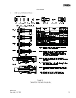
Страница 23: ...Revision A November 25 1996 3 1 SECTION III 3 INSTALLATION DRAWINGS Figure 3 1 Typical BNC Connector Assembly ...
Страница 24: ...3 2 Revision A November 25 1996 THIS PAGE INTENTIONALLY LEFT BLANK ...
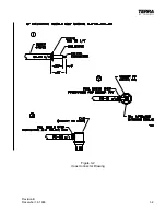
Страница 25: ...Revision B December 16 1996 3 3 Figure 3 2 Coax Connector Drawing ...
Страница 26: ...3 4 Revision A November 25 1996 THIS PAGE INTENTIONALLY LEFT BLANK ...
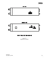
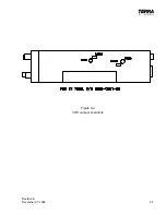
Страница 27: ...Revision A November 25 1996 3 5 Figure 3 3 Adjustment Locations ...
Страница 28: ...3 6 Revision A November 25 1996 THIS PAGE INTENTIONALLY LEFT BLANK ...
Страница 29: ...Revision A November 25 1996 3 7 Figure 3 4 VOX Jumper Locations ...
Страница 30: ...3 8 Revision A November 25 1996 THIS PAGE INTENTIONALLY LEFT BLANK ...
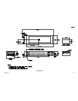
Страница 31: ...Revision A November 25 1996 Figure 3 5 Sheet 1 of 2 Outline Dimensions 3 9 10 ...
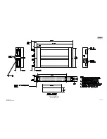
Страница 32: ...Revision A November 25 1996 Figure 3 5 Sheet 2 of 2 Outline Dimensions 3 11 12 ...
Страница 33: ...Revision A November 25 1996 Figure 3 6 Interconnect Diagram 3 13 14 ...
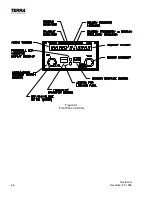
Страница 39: ...4 6 Revision A November 25 1996 Figure 4 1 Front Panel Controls ...
Страница 41: ...5 2 Revision A November 25 1996 THIS PAGE INTENTIONALLY LEFT BLANK ...
Страница 42: ...Revision A November 25 1996 6 1 SECTION VI 6 INSTALLATION BULLETINS NOTES 6 1 INSTALLATION BULLETINS ...
Страница 43: ...6 2 Revision A November 25 1996 6 2 INSTALLATION NOTES ...

