Revision A
November 25, 1996
2-5
2.3.4
NOISE AND INTERFERENCE (CONTINUED)
Conducted interference usually occurs through paths which are shared by the
avionics equipment such as power lines, ground points, audio equipment, or
induced interference between adjacent wires or harnesses. Review the
manufacturer’s recommendations for shielded wiring and ground points, and
for separation of specific wires. Measure ground points for a small but
perceptible resistance to true ground and view power lines with an
oscilloscope, turning each unit on and off to detect changes. Recheck
common or adjacent connections to jacks, plugs, or shared equipment such as
power converters, breakers, or audio panels.
4.
Compromise: In some cases noise or interference may be subdued but not
eliminated. With the inefficient and imperfect platform provided by the
aircraft for antennas and power source, etc, complete elimination of the
problem may be very expensive or impossible (eg. if there is simply not
enough space to provide ground plane or antenna separation as
recommended). Or, the aircraft strobe noise is audible but not objectionable,
etc. These problems should be discussed early and thoroughly with the
customer.
2.3.5
SUMMARY
The paragraphs above are not intended to be highly technical, completely thorough,
or extensive, but serve as a reminder for certain precautionary or follow-up
procedures for general avionics installations. Trimble is prepared to assist at any
point with additional information, hints, or literature. Simply call 1-800-487-4662
and ask for technical assistance.
2.4
INSTALLATION
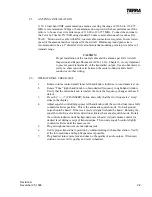
Installation of any equipment in an aircraft requires that the work be performed by a
Certificated Radio Repair Station with appropriate ratings. The installing agency must
complete an FAA Form 337 and compute a new weight and balance for the aircraft for
insertion in the Aircraft Flight Manual. Unless the mechanic is the designated inspector for a
Certificated Radio Repair Station or holds an Inspection Authorization, the work is subject to
inspection and approval by an FAA inspector or the holder of an Inspection Authorization.
Содержание TX 760D
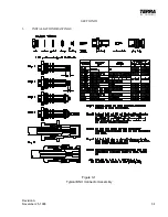
Страница 23: ...Revision A November 25 1996 3 1 SECTION III 3 INSTALLATION DRAWINGS Figure 3 1 Typical BNC Connector Assembly ...
Страница 24: ...3 2 Revision A November 25 1996 THIS PAGE INTENTIONALLY LEFT BLANK ...
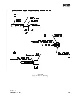
Страница 25: ...Revision B December 16 1996 3 3 Figure 3 2 Coax Connector Drawing ...
Страница 26: ...3 4 Revision A November 25 1996 THIS PAGE INTENTIONALLY LEFT BLANK ...
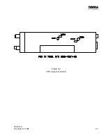
Страница 27: ...Revision A November 25 1996 3 5 Figure 3 3 Adjustment Locations ...
Страница 28: ...3 6 Revision A November 25 1996 THIS PAGE INTENTIONALLY LEFT BLANK ...
Страница 29: ...Revision A November 25 1996 3 7 Figure 3 4 VOX Jumper Locations ...
Страница 30: ...3 8 Revision A November 25 1996 THIS PAGE INTENTIONALLY LEFT BLANK ...
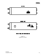
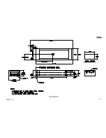
Страница 31: ...Revision A November 25 1996 Figure 3 5 Sheet 1 of 2 Outline Dimensions 3 9 10 ...
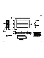
Страница 32: ...Revision A November 25 1996 Figure 3 5 Sheet 2 of 2 Outline Dimensions 3 11 12 ...
Страница 33: ...Revision A November 25 1996 Figure 3 6 Interconnect Diagram 3 13 14 ...
Страница 39: ...4 6 Revision A November 25 1996 Figure 4 1 Front Panel Controls ...
Страница 41: ...5 2 Revision A November 25 1996 THIS PAGE INTENTIONALLY LEFT BLANK ...
Страница 42: ...Revision A November 25 1996 6 1 SECTION VI 6 INSTALLATION BULLETINS NOTES 6 1 INSTALLATION BULLETINS ...
Страница 43: ...6 2 Revision A November 25 1996 6 2 INSTALLATION NOTES ...

