2-6
Revision A
November 25, 1996
2.4
INSTALLATION (CONTINUED)
The following items and suggestions should be considered prior to installation or the Terra
by Trimble TX 760D Transceiver:
1.
Discuss the location of this transceiver with your customer, preferably in a
position that provides ease of operation. The location of the TX 760D in
relation to the pilot’s viewing angle is very important. Due to the small size
of the TX 760D, the vertical viewing angle for the display should not exceed
30 degrees.
2.
Avoid installing the TX 760D near heat sources. If unavoidable, insure
additional cooling is provided.
3.
Insure that adequate clearance exists behind the panel for connectors, cable
bends, and additional cooling if required. A minimum of 14" (35.56 cm) is
recommended.
4.
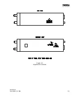
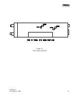
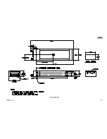
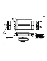
Refer to Terra by Trimble TX 760D outline drawings for panel cut-out
details and mounting dimensions as well as pertinent notes.
5.
Install the sleeve assembly in the instrument panel. Insure compliance with
standards set forth in FAA Aircraft Inspection and Repair Document AC
43.13-2A.
NOTE:
Ensure that the sleeve is installed with the largest opening toward the top.
6.
The 15 pin “D” connector assembly supplied with the Terra by Trimble TX
760D must be wired correctly to the aircraft avionics systems or severe
damage may result to the Terra by Trimble TX 760D or other systems. The
interconnecting wiring for the 15 pin “D” connector is shown in Figure 3-6.
Comply with standards set forth in FAA Aircraft Inspection and Repair
Document AC 43.13-1A Section 7 and other pertinent FAR’s as required.
Insure mil-spec wire is utilized for all interconnects.
NOTE:
It is recommended that the TX 760D be installed and locked into the
mounting sleeve before tying and securing the wiring harness. This will
ensure proper alignment of the “floating” connectors to facilitate easy
removal and installation of the TX 760D.
CAUTION!
The operating voltage of this Terra by Trimble TX 760D is 13.75 V nominal
for direct connection to an aircraft 12-14 volt electrical system. If the
aircraft electrical system supply is 24-28 volt, it is necessary to employ a
converter to reduce the 28 volts to 13.75 volts for the Terra by Trimble TX
760D. Trimble can supply an optional converter specifically designed for
this purpose. It is Terra by Trimble P/N 0900-3219-12, Model MLC 28-5.
Содержание TX 760D
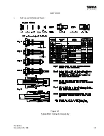
Страница 23: ...Revision A November 25 1996 3 1 SECTION III 3 INSTALLATION DRAWINGS Figure 3 1 Typical BNC Connector Assembly ...
Страница 24: ...3 2 Revision A November 25 1996 THIS PAGE INTENTIONALLY LEFT BLANK ...
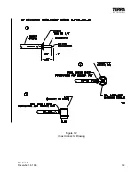
Страница 25: ...Revision B December 16 1996 3 3 Figure 3 2 Coax Connector Drawing ...
Страница 26: ...3 4 Revision A November 25 1996 THIS PAGE INTENTIONALLY LEFT BLANK ...
Страница 27: ...Revision A November 25 1996 3 5 Figure 3 3 Adjustment Locations ...
Страница 28: ...3 6 Revision A November 25 1996 THIS PAGE INTENTIONALLY LEFT BLANK ...
Страница 29: ...Revision A November 25 1996 3 7 Figure 3 4 VOX Jumper Locations ...
Страница 30: ...3 8 Revision A November 25 1996 THIS PAGE INTENTIONALLY LEFT BLANK ...
Страница 31: ...Revision A November 25 1996 Figure 3 5 Sheet 1 of 2 Outline Dimensions 3 9 10 ...
Страница 32: ...Revision A November 25 1996 Figure 3 5 Sheet 2 of 2 Outline Dimensions 3 11 12 ...
Страница 33: ...Revision A November 25 1996 Figure 3 6 Interconnect Diagram 3 13 14 ...
Страница 39: ...4 6 Revision A November 25 1996 Figure 4 1 Front Panel Controls ...
Страница 41: ...5 2 Revision A November 25 1996 THIS PAGE INTENTIONALLY LEFT BLANK ...
Страница 42: ...Revision A November 25 1996 6 1 SECTION VI 6 INSTALLATION BULLETINS NOTES 6 1 INSTALLATION BULLETINS ...
Страница 43: ...6 2 Revision A November 25 1996 6 2 INSTALLATION NOTES ...

