1-4
Revision A
November 25, 1996
1.4.1
OPTIONAL EQUIPMENT
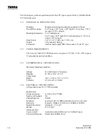
Noise-canceling Microphone, Carbon, Push-to-talk
Terra by Trimble P/N 0900-0151-01
Voltage Converter 27.50 to 13.75 V
Model MLC 28-5 Terra by Trimble P/N 0900-3219-12
Push-to-talk Switch
Terra by Trimble P/N 0900-0203-01
Headset with Microphone
Terra by Trimble P/N 0900-0201-11
Ext. VOX Kit, Pot. and Knobs
Terra by Trimble P/N 1901-5322-00
1.5
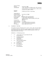
ADDITIONAL EQUIPMENT REQUIRED
1.
Sufficient RG 58A/U 50 co-axial antenna cable to reach from the transceiver to the
antenna. BNC co-axial fittings as required for the particular installation. If cable
length exceeds 20 feet RG8 co-axial cable is recommended
2.
MIL 22759 or equivalent wire sufficient to make the harness.
3.
Microphone and headphone jacks as required.
4.
Circuit breaker rated at 4 amps.
5.
50 ohm communications antenna rated at top speed of the aircraft.
1.6
LICENSE REQUIREMENTS
The operator of the Terra by Trimble TX 760D transceiver is required by the Federal
Communications Commission to hold a restricted radio-telephone operator’s permit, or a
higher class of license. A U.S. citizen may obtain the operator permit from the nearest FCC
office.
The transceiver, when installed in an aircraft, requires an Aircraft Radio Station License.
This license may be obtained by filing an FCC Form 404. The transceiver should be identified
on the form as CCXTX760D under Type Acceptance Number. If a copy of the filed Form
404 is kept in the aircraft, the TX 760D may be operated up to 30 days while awaiting the
formal license.
For Ground Station operation, Form 406 should be filed as above.
Содержание TX 760D
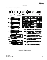
Страница 23: ...Revision A November 25 1996 3 1 SECTION III 3 INSTALLATION DRAWINGS Figure 3 1 Typical BNC Connector Assembly ...
Страница 24: ...3 2 Revision A November 25 1996 THIS PAGE INTENTIONALLY LEFT BLANK ...
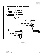
Страница 25: ...Revision B December 16 1996 3 3 Figure 3 2 Coax Connector Drawing ...
Страница 26: ...3 4 Revision A November 25 1996 THIS PAGE INTENTIONALLY LEFT BLANK ...
Страница 27: ...Revision A November 25 1996 3 5 Figure 3 3 Adjustment Locations ...
Страница 28: ...3 6 Revision A November 25 1996 THIS PAGE INTENTIONALLY LEFT BLANK ...
Страница 29: ...Revision A November 25 1996 3 7 Figure 3 4 VOX Jumper Locations ...
Страница 30: ...3 8 Revision A November 25 1996 THIS PAGE INTENTIONALLY LEFT BLANK ...
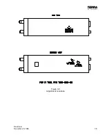
Страница 31: ...Revision A November 25 1996 Figure 3 5 Sheet 1 of 2 Outline Dimensions 3 9 10 ...
Страница 32: ...Revision A November 25 1996 Figure 3 5 Sheet 2 of 2 Outline Dimensions 3 11 12 ...
Страница 33: ...Revision A November 25 1996 Figure 3 6 Interconnect Diagram 3 13 14 ...
Страница 39: ...4 6 Revision A November 25 1996 Figure 4 1 Front Panel Controls ...
Страница 41: ...5 2 Revision A November 25 1996 THIS PAGE INTENTIONALLY LEFT BLANK ...
Страница 42: ...Revision A November 25 1996 6 1 SECTION VI 6 INSTALLATION BULLETINS NOTES 6 1 INSTALLATION BULLETINS ...
Страница 43: ...6 2 Revision A November 25 1996 6 2 INSTALLATION NOTES ...


