Revision A
November 25, 1996
1-3
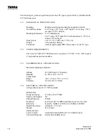
Adjacent Channel
Rejection:
Greater than 60dBm.
Auxiliary Inputs:
3 inputs with minimum of 30dBm isolation. One volt input at
1 Khz will produce one volt output across a 3.2 ohm resistor
connected to the speaker terminals.
Incidental
Radiation:
Certified per FCC Part 15 requirements.
TRANSMITTER
Frequency Range:
118.00 to 136.975 MHz
Number of Channels:
760
Frequency Stability:
+0.002% per FCC Type Acceptance.
Power Output:
5 watts nominal, unmodulated carrier.
Modulation:
Automatic audio leveling for a minimum of 80% and a
maximum of 95%.
Emmision Type:
6K00A3E
Output Termination:
50 nominal.
Spurious Responses:
Greater than 50 dBm below carrier level.
Sidetone:
Up to 25 milliwatts into 600 headphones.
FCC Approval:
Type accepted per FCC Part 87.
1.4
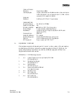
EQUIPMENT SUPPLIED
The equipment supplied will depend upon the “system” you have ordered. The part numbers
and descriptions listed below indicate the equipment supplied with the TX 760D only. If a
system other than those listed below was ordered, additional equipment will have been
supplied and listed in another manual.
0990-0405-10
TX 760D, Single System
1.
1ea
Comm Transceiver, Terra by Trimble TX 760D
P/N 1900-0361-00
2.
1ea
Mounting Tray, Single
P/N 1900-0357-10
3.
1ea
Installation Kit
P/N 1901-2671-10
4.
1ea
Operation/Installation Manual
TX 760D P/N 82619
5.
1ea
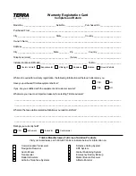
Warranty Card
6.
1ea
FCC Form 404
P/N 1900-0607-00
7.
1ea
FCC Form 406
P/N 1900-0608-00
Содержание TX 760D
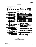
Страница 23: ...Revision A November 25 1996 3 1 SECTION III 3 INSTALLATION DRAWINGS Figure 3 1 Typical BNC Connector Assembly ...
Страница 24: ...3 2 Revision A November 25 1996 THIS PAGE INTENTIONALLY LEFT BLANK ...
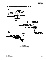
Страница 25: ...Revision B December 16 1996 3 3 Figure 3 2 Coax Connector Drawing ...
Страница 26: ...3 4 Revision A November 25 1996 THIS PAGE INTENTIONALLY LEFT BLANK ...
Страница 27: ...Revision A November 25 1996 3 5 Figure 3 3 Adjustment Locations ...
Страница 28: ...3 6 Revision A November 25 1996 THIS PAGE INTENTIONALLY LEFT BLANK ...
Страница 29: ...Revision A November 25 1996 3 7 Figure 3 4 VOX Jumper Locations ...
Страница 30: ...3 8 Revision A November 25 1996 THIS PAGE INTENTIONALLY LEFT BLANK ...
Страница 31: ...Revision A November 25 1996 Figure 3 5 Sheet 1 of 2 Outline Dimensions 3 9 10 ...
Страница 32: ...Revision A November 25 1996 Figure 3 5 Sheet 2 of 2 Outline Dimensions 3 11 12 ...
Страница 33: ...Revision A November 25 1996 Figure 3 6 Interconnect Diagram 3 13 14 ...
Страница 39: ...4 6 Revision A November 25 1996 Figure 4 1 Front Panel Controls ...
Страница 41: ...5 2 Revision A November 25 1996 THIS PAGE INTENTIONALLY LEFT BLANK ...
Страница 42: ...Revision A November 25 1996 6 1 SECTION VI 6 INSTALLATION BULLETINS NOTES 6 1 INSTALLATION BULLETINS ...
Страница 43: ...6 2 Revision A November 25 1996 6 2 INSTALLATION NOTES ...


