Revision A
November 25, 1996
2-7
NOTE:
a.
If a loudspeaker is not used it will be necessary to connect a 15 ohm
3 watt resistor across the speaker terminals (pin 12 and pin 15) of the
15 pin “D” connector. Failure of the output circuit could occur if
this load is not installed.
b.
If the installation is a retrofit of a TX 720, care must be taken to
properly rewire the connector or damage and incorrect operation will
result.
7.
Should the customer desire the VOX Intercom feature, it is recommended
that a relay be used in the manner described on the Interconnect Diagram,
Figure 3-6. If this is not done, the co-pilot’s microphone will be “hot” during
transmit and both mic audio signals will be transmitted simultaneously.
8.
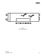
Another option for use with the VOX Intercom feature is an external VOX
Intercom squelch adjustment. This requires a potentiometer (100 k , 1/4 W)
to be installed as per Note #5 on Figure 3-6. When using this option on
Units, the Vox Intercom squelch adjustment on the TX 760D must be turned
fully CCW and shorting jumper SJ601 must be removed for proper
operation. SJ601 can be located on drawing Figure 3-4.
9.
Yet another option for use with the VOX Intercom feature is an external
VOX Intercom volume adjustment. This requires a potentiometer (10 k , 1/4
W, Audio taper) to be installed as per note #6 on Figure 3-6. When using
this option, the VOX Intercom volume adjustment on the TX 760D must be
fully CW and shorting jumper SJ602 removed for proper operation. SJ602
can be located using component locator Figure 3-4.
10.
Install the TX 760D in the mounting sleeve assembly. Use caution as the
rear connectors mate. After the float mounts are positioned correctly, (a little
twisting at the front panel may be necessary), the unit will fully engage the
connectors with light to medium pressure on the front panel.
CAUTION:
DO NOT PUSH UNIT INTO SLEEVE WITH THUMBS ON LENS AS
DISPLAY DAMAGE MAY RESULT!
Insert a 7/64" Allen wrench in the front panel hole and engage the locking screw.
Turn clockwise until the cam has engaged itself in the sleeve and is moderately
tightened. Use caution to prevent stripping the threads on the locking cam or screw.
To remove the unit from the mounting sleeve, insert the 7/64" Allen wrench in the
locking screw and turn counterclockwise. The cam will move the unit outward about
1/4" and disengage the connectors. The unit may now be pulled out of the mounting
sleeve by hand.
Содержание TX 760D
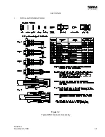
Страница 23: ...Revision A November 25 1996 3 1 SECTION III 3 INSTALLATION DRAWINGS Figure 3 1 Typical BNC Connector Assembly ...
Страница 24: ...3 2 Revision A November 25 1996 THIS PAGE INTENTIONALLY LEFT BLANK ...
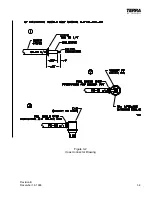
Страница 25: ...Revision B December 16 1996 3 3 Figure 3 2 Coax Connector Drawing ...
Страница 26: ...3 4 Revision A November 25 1996 THIS PAGE INTENTIONALLY LEFT BLANK ...
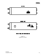
Страница 27: ...Revision A November 25 1996 3 5 Figure 3 3 Adjustment Locations ...
Страница 28: ...3 6 Revision A November 25 1996 THIS PAGE INTENTIONALLY LEFT BLANK ...
Страница 29: ...Revision A November 25 1996 3 7 Figure 3 4 VOX Jumper Locations ...
Страница 30: ...3 8 Revision A November 25 1996 THIS PAGE INTENTIONALLY LEFT BLANK ...
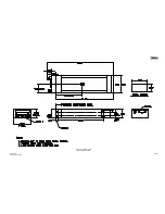
Страница 31: ...Revision A November 25 1996 Figure 3 5 Sheet 1 of 2 Outline Dimensions 3 9 10 ...
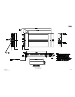
Страница 32: ...Revision A November 25 1996 Figure 3 5 Sheet 2 of 2 Outline Dimensions 3 11 12 ...
Страница 33: ...Revision A November 25 1996 Figure 3 6 Interconnect Diagram 3 13 14 ...
Страница 39: ...4 6 Revision A November 25 1996 Figure 4 1 Front Panel Controls ...
Страница 41: ...5 2 Revision A November 25 1996 THIS PAGE INTENTIONALLY LEFT BLANK ...
Страница 42: ...Revision A November 25 1996 6 1 SECTION VI 6 INSTALLATION BULLETINS NOTES 6 1 INSTALLATION BULLETINS ...
Страница 43: ...6 2 Revision A November 25 1996 6 2 INSTALLATION NOTES ...

