Revision A
November 25, 1996
4-1
SECTION IV
4.
OPERATION
4.1
SCOPE
This section covers operation procedures for the TX760D.
4.2
OPERATION
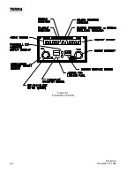
See Figure 4-1 for locations and descriptions of the TX 760D Front Panel Controls.
CAUTION!
Ensure the TX 760D is turned off until after engine start-up procedures are
completed. This simple precaution will greatly improve the lifetime of all of
your avionics as well as your new TX 760D.
4.3
FREQUENCY MODE
To turn power on, rotate the small inner left knob clockwise. A slight detent will be felt.
The following will be displayed in the window:
188.88 T/R 8 m 188.88
After 5 seconds the displays will revert back to the last used frequencies.
Enter your desired frequency in the right hand or “standby” window, by turning the tune knob
on the right-hand side. Clockwise tuning increases the frequency and counterclockwise
tuning decreases the frequency. At the upper and lower limits of the frequency band i.e.,
118.00 and 136.975, the frequency will “wrap around”. This allows faster tuning from one
end of the band to the other.
After the desired frequency is obtained, simply press the <—> (TRANSFER) button to move
the new frequency into the left-hand or “active” window and your previously used frequency
to the right-hand or “standby” window.
4.4
NORMAL OPERATION
Rotate the squelch (large left-hand outer) knob clockwise until background noise is heard.
Rotate the volume (small left-hand inner knob) until this noise corresponds to a desired
listening level.
Rotate the squelch knob counterclockwise until a detent is felt. This places the TX 760D in
the “auto squelch” mode.
With the desired frequency entered in the left-hand (ACTIVE) window as described above,
key your microphone and you will be transmitting on the active frequency. Releasing the key
will automatically place your TX 760D in the receive mode.
Содержание TX 760D
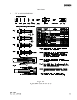
Страница 23: ...Revision A November 25 1996 3 1 SECTION III 3 INSTALLATION DRAWINGS Figure 3 1 Typical BNC Connector Assembly ...
Страница 24: ...3 2 Revision A November 25 1996 THIS PAGE INTENTIONALLY LEFT BLANK ...
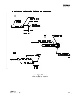
Страница 25: ...Revision B December 16 1996 3 3 Figure 3 2 Coax Connector Drawing ...
Страница 26: ...3 4 Revision A November 25 1996 THIS PAGE INTENTIONALLY LEFT BLANK ...
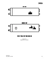
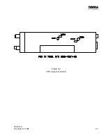
Страница 27: ...Revision A November 25 1996 3 5 Figure 3 3 Adjustment Locations ...
Страница 28: ...3 6 Revision A November 25 1996 THIS PAGE INTENTIONALLY LEFT BLANK ...
Страница 29: ...Revision A November 25 1996 3 7 Figure 3 4 VOX Jumper Locations ...
Страница 30: ...3 8 Revision A November 25 1996 THIS PAGE INTENTIONALLY LEFT BLANK ...
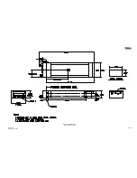
Страница 31: ...Revision A November 25 1996 Figure 3 5 Sheet 1 of 2 Outline Dimensions 3 9 10 ...
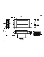
Страница 32: ...Revision A November 25 1996 Figure 3 5 Sheet 2 of 2 Outline Dimensions 3 11 12 ...
Страница 33: ...Revision A November 25 1996 Figure 3 6 Interconnect Diagram 3 13 14 ...
Страница 39: ...4 6 Revision A November 25 1996 Figure 4 1 Front Panel Controls ...
Страница 41: ...5 2 Revision A November 25 1996 THIS PAGE INTENTIONALLY LEFT BLANK ...
Страница 42: ...Revision A November 25 1996 6 1 SECTION VI 6 INSTALLATION BULLETINS NOTES 6 1 INSTALLATION BULLETINS ...
Страница 43: ...6 2 Revision A November 25 1996 6 2 INSTALLATION NOTES ...


