TELOS 2101 USER’S MANUAL
PART IV
THE STUDIO INTERFACE & ADDITIONAL HYBRIDS
IV-11
SECTION 1 – STUDIO INTERFACE INSTALLATION
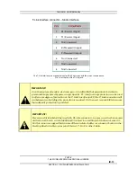
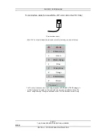
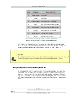
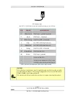
T-Link interface connector – Studio Interface
PIN
FUNCTION
1
R1 (Receive/Input)
2 T1
(Receive/Input)
3
Not Connected
4 R
(Transmit/Output)
5
T (Transmit/Output)
6
Not Connected
7
Not Connected
8 Not
Connected
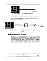
The T-Link interface is a standard modular RJ-45 style jack with the pin-out shown above.
Pin 1 is at the top of the T-Link jack.
w
IMPORTANT!
As with any piece of modern electronic gear, it is advisable that precautions be taken to
prevent damage caused by power surges. Special “T1” interface surge protectors can be used
to offer some degree of protection at the T- Link interface jack. If the T- Link connection will
run between two buildings this protection is required. It is the user’s responsibility to ensure
that adequate protection is provided
.
e
IMPORTANT!
Be very careful to label wiring used with RJ- style connectors. In some cases they have power
on them, and there is a risk of applying this power to something which does not expect it.
For this reason we suggest that you use different colored cables (or connector boots) on the
Desktop Director cables versus your Ethernet, T- Link, & other Cables.


