


xE922-3GR Hardware User Guide
1VV0301272
Rev.0.8 2017-01-05
Reproduction forbidden without written authorization from Telit Communications S.p.A. - All Rights
Reserved.
Page 76 of 112
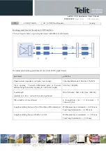
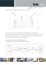
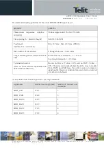
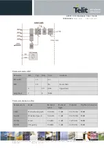
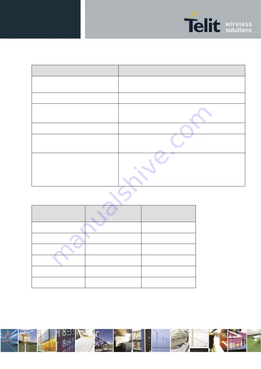
Recommended routing guidelines for the whole SDMMC/SDIO signal traject:
parameter
guideline
Characteristic impedance (stripline /
microstrip)
50 ohm single ended 10%(SL) 15%(MS)
Trace spacing (h = dielectric height)
2xh (SL) 3xh (MS)
Total length
(module (L1) + carrier(L2))
Min. 12.7 mm / Max. 88.9 mm (MS/SL)
Max. number of vias allowed
4 through-hole vias + 3 microvias
Length matching between DATA/CMD to
CLK
Within same layer mismatch : +/- 1.27 mm
Total length mismatch: +/- 2.54 mm
Termination resistors
(Note: no series resistors implemented on
xE922-3GR module side )
Rseries on CLK is 27 ohm +/-10%, and on DAT 39 ohm +/-
10%. The series resistor placeholder should be close to module
CLK, DATA and CMD lanes. Use of the resistor is to improve
signal quality .Based on validation data, resistor can be removed
or retained on the board
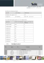
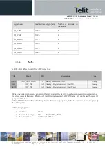
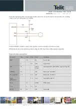
Actual xE922-3GR module signal trace (L1) implementation:
signal name
module trace length [mm]
Number of microvias on
the module
SDIO_CLK
18.81
3
SDIO_CMD
18.40
5
SDIO_DAT0
19.85
3
SDIO_DAT1
18.39
4
SDIO_DAT2
17.65
4
SDIO_DAT3
17.62
4