


xE922-3GR Hardware User Guide
1VV0301272
Rev.0.8 2017-01-05
Reproduction forbidden without written authorization from Telit Communications S.p.A. - All Rights
Reserved.
Page 60 of 112
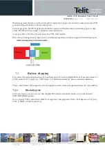
10.
Display interface
The xE922-3GR supports a display according following 3 interface types:
·
MIPI-DSI (4-lane, GPIO
’s including
tearing effect timing control)
·
LVDS (4-lane)
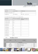
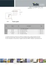
On top of this display interface the module also features backlight control (CABC input, BL feedback input, BL
drive output) and I2C port to control a touch panel IC.
LCD_RESET and LCD_TE interface pins become available as general GPIO function in case no LCD feature
implemented in the system.
Please consult Intel’s IBL Support website for AVL (approved vendor list), as well
for recommended
implementation and port assignment
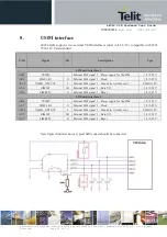
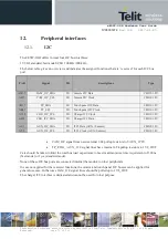
10.1.
MIPI-DSI
4-lane MIPI DSI compliant, utilizing MIPI DPHY as physical layer.
Max rate of bit clock of a DPHY lane is defined as 400MHz, or equivalent data rate 800Mbps.
PAD
Signal
I/O
descriptions
Type
MIPI DSI Display Interface
S19
DSI_DP0
AO
LCD DSI Data_0 Positive
Analog
P19
DSI_DN0
AO
LCD DSI Data_0 Negative
Analog
R20
DSI_DP1
AO
LCD DSI Data_1 Positive
Analog
N20
DSI_DN1
AO
LCD DSI Data_1 Negative
Analog
L20
DSI_DP2
AO
LCD DSI Data_2 Positive
Analog
J20
DSI_DN2
AO
LCD DSI Data_2 Negative
Analog
K21
DSI_DP3
AO
LCD DSI Data_3 Positive
Analog
H21
DSI_DN3
AO
LCD DSI Data_3 Negative
Analog
M21
DSI_CLKP
AO
LCD DSI Clock Positive
Analog
P21
DSI_CLKN
AO
LCD DSI Clock Negative
Analog
AP11
LCD_RESET
I/O
LCD Reset / GPIO
CMOS 1.8V
AP9
LCD_TE
I/O
LCD Tearing effect input
CMOS 1.8V
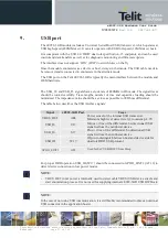
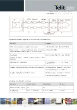
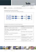
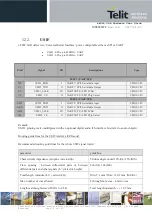
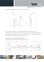
Routing guide lines for the display MIPI-DSI interface:
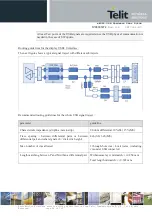
The next figure shows a typical signal traject with different sub trajects.