


xE922-3GR Hardware User Guide
1VV0301272
Rev.0.8 2017-01-05
Reproduction forbidden without written authorization from Telit Communications S.p.A. - All Rights
Reserved.
Page 39 of 112
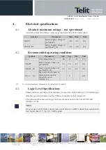
4.
Electrical specifications
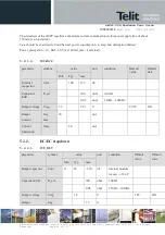
4.1.
Absolute maximum ratings
–
not operational
A deviation from listed below values range may harm the xE922-3GR module.
Symbol
Parameter
Min
Max
Unit
VBATT
battery supply voltage on
pin VBATT
-0.3
+5.5
[V]
VBATT_PA
battery supply voltage on
pin VBATT_PA
-0.3
+6.0
[V]
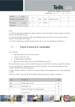
4.2.
Recommended operating conditions
Symbol
Parameter
Min
Typ
Max
Unit
T
case
Case temperature (1)
-40
+25
+85
[°C]
VBATT
Battery supply voltage on
pin VBATT
3.6
3.8
4.2
[V]
VBATT_PA
Battery supply voltage on
pin VBATT_PA
3.6
3.8
4.2
[V]
I
B
I
BATT
Peak current to be used to
dimension decoupling
capacitors on pin
VBATT_PA
-
2
-
[A]
(1)
T
case
case temperature: measured at top side shield of module
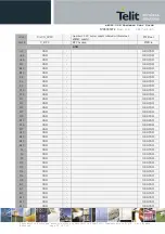
4.3.
Logic Level Specifications
Unless otherwise specified, all the interface circuits of the xE922-3GR are 1.8V CMOS logic.
Only few specific interfaces (such as USIM) are capable of dual voltage I/O.
The following table shows the logic level specifications used in the Telit xE922-3GR
interface circuits:
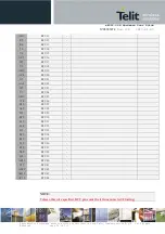
NOTE:
Do not connect xE922-3GR
’s digital logic signal directly to OEM’s digital logic signal with a
level higher than 2.1V for 1.8V CMOS signals.