


xE922-3GR Hardware User Guide
1VV0301272
Rev.0.8 2017-01-05
Reproduction forbidden without written authorization from Telit Communications S.p.A. - All Rights
Reserved.
Page 58 of 112
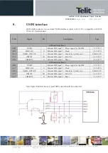
At least Test point of the USB signals are required since the USB physical communication is
needed in the case of SW update.
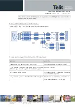
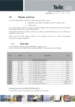
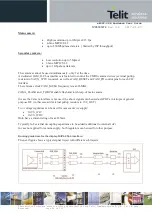
Routing guide lines for the display USB2.0 interface:
The next figure shows a typical signal traject with different sub trajects.
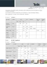
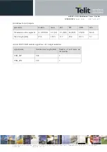
Recommended routing guidelines for the whole USB signal traject :
parameter
guideline
Characteristic impedance (stripline / microstrip)
90 ohm differential 10%(SL) 15%(MS)
Trace spacing : between differential pairs or between
differential pair and other signals (h = dielectric height)
4xh (SL) 6xh (MS)
Max. number of vias allowed
3 through-hole vias + 4 microvias (including
via under USB connector)
Length matching between P and N within a differential pair
Within same layer mismatch: +/-0.254 mm
Total length mismatch: +/-0.381 mm